 |
|||
|
|
|||
|
|
|||
| ||||||||||
|
|
 TM 5-5430-209-12
(c) The inside flange (3) is countersunk to
receive the boltheads. Insert bolts (2) in inside flange
half (3). Place 4-hole gasket (4) over the bolts and
against the flange half.
(d) Install assembled flange half in stave (5)
from inside the tank.
(e) On outside of tank, install gasket (1, fig. 6-
21) over bolts (2) and against stave (3).
(f) Install outside flange half (4) over bolts and
against gasket (1). Install nuts (5) on bolts and tighten
securely.
(2) Valve and Nipple.
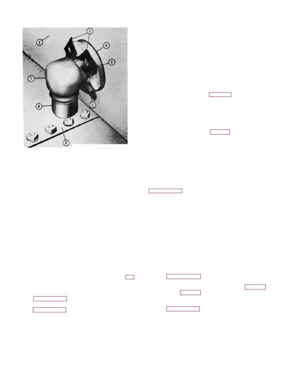
(a) The nipple (6, fig. 6-22) must be cut to
length so that clearance between nipple and tank bottom
(8) is 1-inch.
(b) Install nipple (6) in elbow (7).
(c) Install elbow in inside flange half (3).
Tighten elbow until nipple is vertical and the opening
faces the tank bottom.
(d) Install valve (7, fig. 6-21) in outside flange
half (4). Tighten valve until the opening is vertical and
faces the chime.
6-20. Tank Outlets
1. GASKET
a. General. The tank is equipped with three
2. FLANGE BOLT
special staves for installation of outlets. Two staves are
3. INSIDE FLANGE HALF
made to contain 8-inch outlets, and the third a 6-inch
4. GASKET
outlet. Each outlet consists of a 90 elbow, a pipe
5. STAVE
flange set, and a grooved-type coupling.
6. NIPPLE
b. Installation. Procedures for installing the 6-and
7. ELBOW
8-inch outlet components' are identical.
Refer to
8. TANK BOTTOM
ME 5430-209.12/6-22.
Figure 6-22. Water drawoff valve elbow and
nipple installed inside tank.
Section VI. TANK TESTING AND FINAL ASSEMBLY
6-21. General
16-124. Cleanout Cover
The tank interior must be cleaned, inspected, and tested
Refer to paragraph 3-27 and install the cleanout cover.
for leakage prior to installation of cleanout cover (14, fig.
NOTE
1-3). After installation of cover, the tank site must be
There are two vertical rows of channels (5. fig. 3-30)
cleaned.
6-22. Tanking Cleaning and Inspection
and boltholes (fig. 3-31) on either side of the cleanout
opening on the 1000-barrel tank.
Refer to paragraph 3-24 and clean and inspect the tank.
6-25. Cleaning the Tank Site
6-23. Water Test
Refer to paragraph 3-28 and clean the tank site.
Refer to paragraph 3-26 and test the tank for leaks.
6-24
|
|
Privacy Statement - Press Release - Copyright Information. - Contact Us |