 |
|||
|
|
|||
|
Page Title:
Section VI. TANK TESTING AND FINAL ASSEMBLY |
|
||
| ||||||||||
|
|
 TM 5-5430-209-12
(b) Install adapter (3, fig. 3-29), made up with
bottom and top halves of coupling (6) in that order.
outside flange (2), over bolts. Install nuts (4) on bolts
Install nuts (8) on bolts and tighten the bolts.
and tighten the bolts.
(d) If a water seal is required because of bottom
(c) Install cap (5), over outlet end of adapter.
leakage, omit elbow (2, fig. 3-28).
Connect coupling (6) to cap. Insert bolts (7) through
Section VI. TANK TESTING AND FINAL ASSEMBLY
3-23. General
The inside of the tank must be cleaned and inspected,
and tank must be tested for leakage prior to installation
of cleanout cover. After installation of cover, tank site
must be cleaned.
3-24. Tank Cleaning and Inspection
a. Tank Bottom.
(1) Sweep bottom of the tank and remove all
debris and foreign matter.
(2) Check bottom seam for breaks or misses
in the sealing compound. Apply compound to bare
spots.
(3) Check for loose or damaged bolts.
Tighten loose bolts and replace damaged bolts.
b. Staves.
(1) Inspect staves from inside the tank for
missing bolts. Make sure all boltheads are seated in the
bolt channels.
(2) Inspect staves from outside the tank for
missing nuts from the lap seam. Tighten all loose nuts.
(3) Replace damaged bolts or nuts.
c. Deck.
(1) Inspect deck plates to see that all seam and
chime nuts are in place and tight.
(2) Tighten all loose nuts. Replace damaged
bolts and nuts.
3-25. Cleanout Cover Bolt Channels and Gaskets
a. General. Special bolt channels with bolt
retainers are installed on the inside top and sides of the
cleanout opening.
b. Installation.
(1) Top Channel.
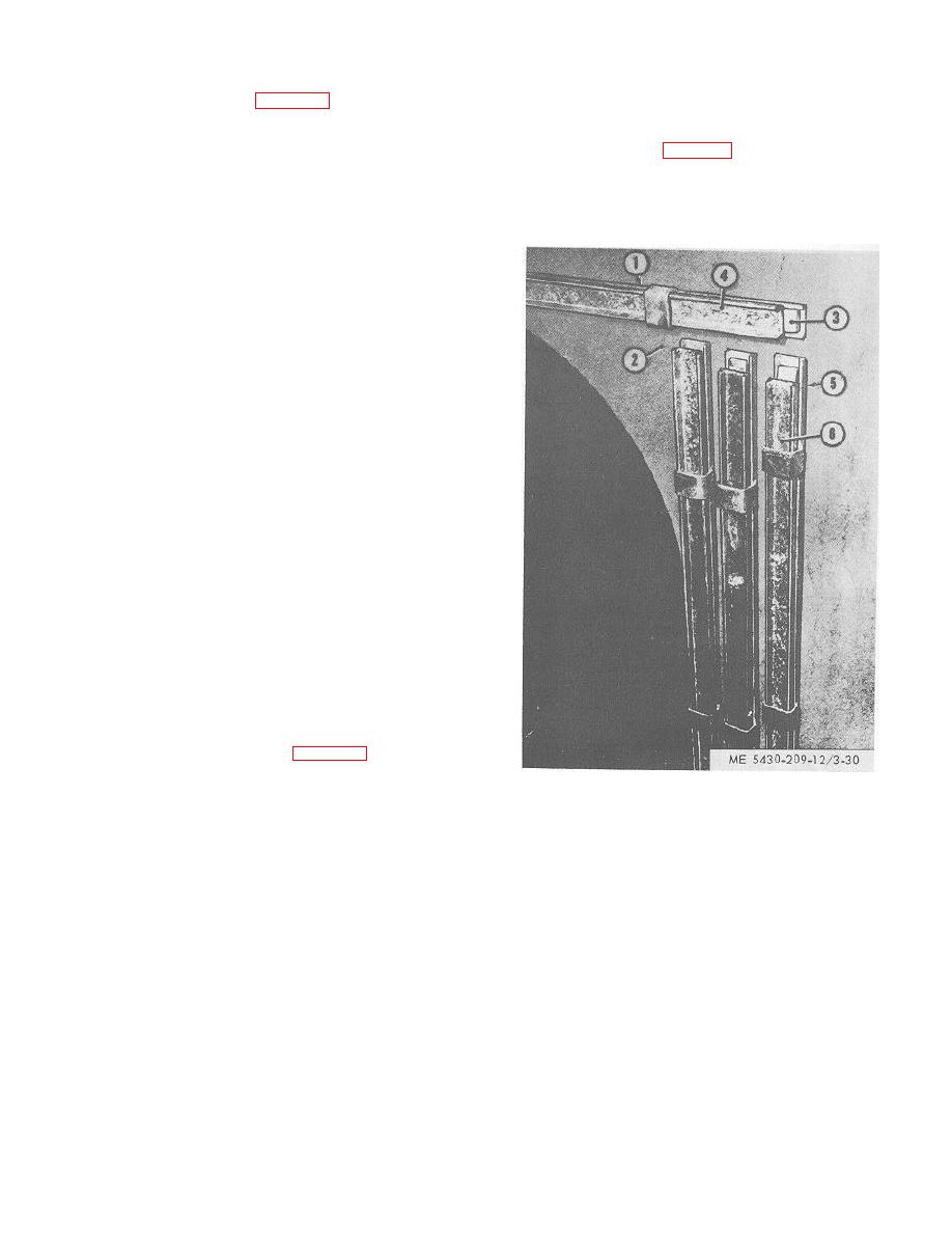
(a) Place a bolt channel (1, fig. 3-30) above the
cleanout opening inside the staves (2). Insert %/2 by 1
1/4-inch bolts (3) through all bolt holes. Be sure bolt
1. BOLT CHANNEL4.
RETAINING CHANNEL
heads are square in the channel.
2. STAVE
5.
BOLT CHANNEL
3. BOLT
6.
RETAINING CHANNEL
Figure 3-30.Bolt. channels for cleanout cover installed
(10,000-barrel capacity tank).
3-26
|
|
Privacy Statement - Press Release - Copyright Information. - Contact Us |
