 |
|||
|
|
|||
|
Page Title:
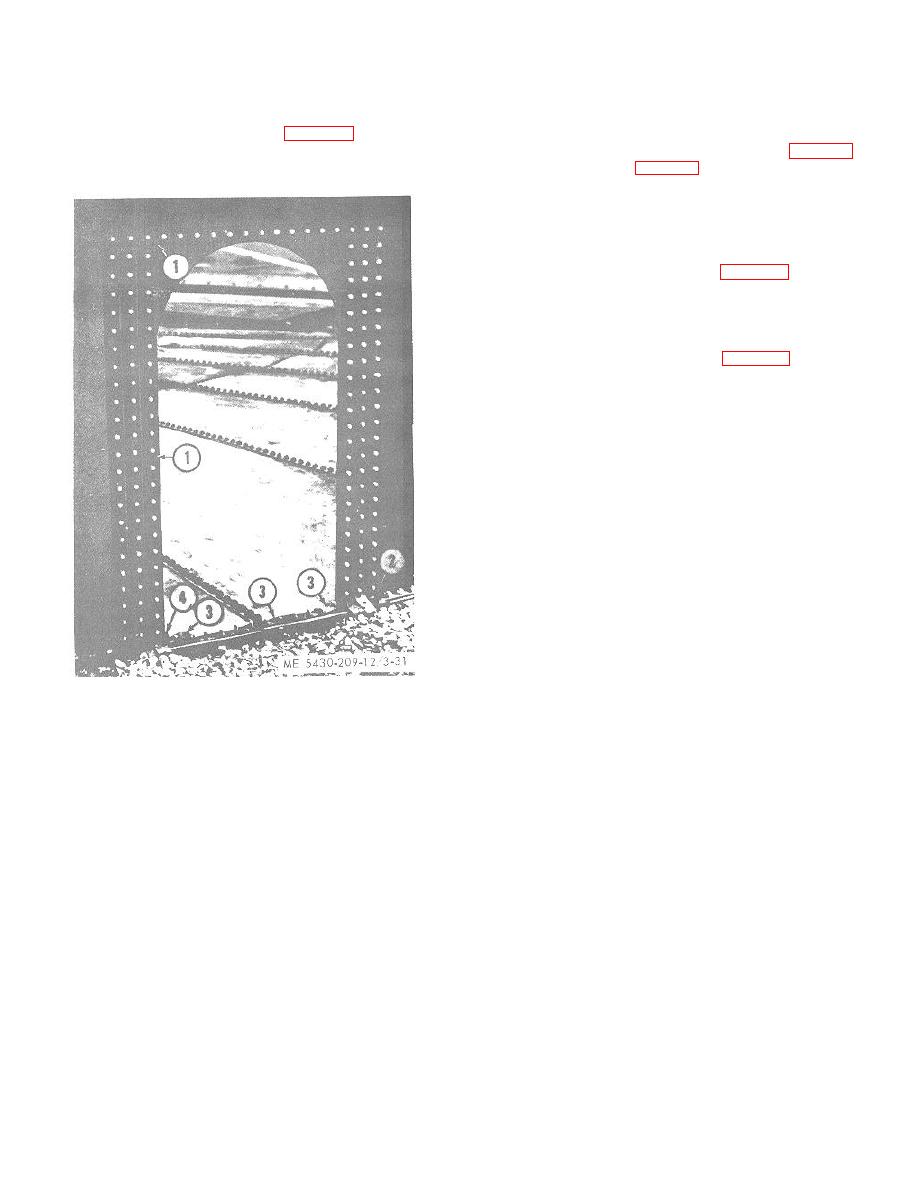
Figure 3-31. Gaskets at cleanout opening installed (10,000 barrel capacity tank). |
|
||
| ||||||||||
|
|
 TM 5-5430-209-12
Side channels.
(2)
(b) Insert retaining channel (4) through clips on the
bolt channel (1).
NOTE
(c) Install a strip gasket (1, fig. 3-31) along full
The 100-, 250-, and 500-barrel tanks contain
length of top seam outside the stave. Allow a 1bolthole
one vertical row of channels (5 and 6, fig. 3-30)
overlap at each end.
and boltholes (fig. 3-31) on each side seam, the
1000and 3000-barrel tanks contain two vertical
rows of channels and boltholes on each side
seam, and the 10,000-barrel tank contains three
vertical rows of channels and boltholes on each
side seam.
(a) Place bolt channel (5, fig. 3-30) inside the
tank on each row of boltholes. Insert bolts (3) through all
boltholes.
(b) Insert retaining channel (6) through clips
on bolt channel (5) to retain the bolts.
(c)
Install strip gasket (1, fig. 3-31) along the
full length of each row of bolts. Pass gaskets under top
seam gasket.
(d) Apply sealing compound at overlap of top
and vertical seam gaskets.
(e) Install radii gaskets (2 and 4) under
vertical seam gaskets at bottom chime of stave.
(f)
Install wedge gaskets (3) at each side of
opening at offset formed by the chime with the bottom
sections.
(g) Recheck wedge gasket at lap formed by the
adjoining bottom sections at center of cleanout opening.
3-26. Water Test
a. Tank Bottom. There are two methods of testing
the bottom for leakage. Both methods require use of a
temporary partial cover on the cleanout opening.
(1) Fabricate a temporary partial cover (fig.
332) for the cleanout opening. Cover must form a liquid-
tight seal over the lower 10 inches of the cleanout
opening.
1.
STRIP GASKET
2.
RADII GASKET
3.
WEDGE GASKET
4.
RADII GASKET
Figure 3-31. Gaskets at cleanout opening installed
(10.000 barrel capacity tank).
3-27
|
|
Privacy Statement - Press Release - Copyright Information. - Contact Us |