 |
|||
|
|
|||
|
Page Title:
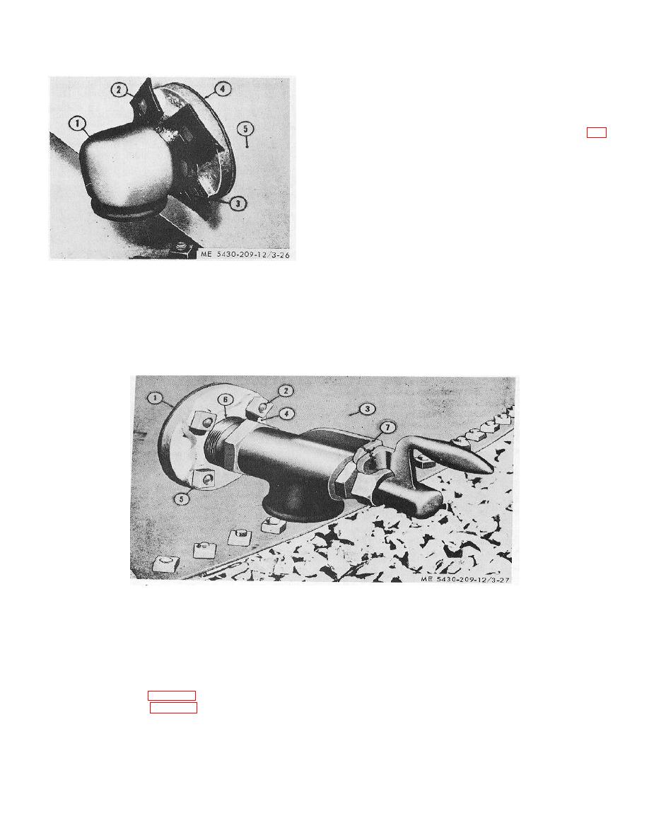
Figure 3-27. Water drawoff valve installed on outside of tank |
|
||
| ||||||||||
|
|
 TM 5-5430-209-12
(a) Cut four 1-inch gaskets (2). Force gaskets over
bolts (3).
(b) Install bolts through flange of elbow (1).
Place blocking under heads of bolts. Install gasket
(4) over the bolts.
(c) Turn elbow inlet toward tank bottom.
Insert bolts (3) through stave (5). Install nuts (5, fig.
3-27) temporarily on two bolts (2) while assembling
valve (7). Remove nuts before installing valve.
1.
FLANGED ELBOW
2.
ONE-HOLE GASKFT
3.
BOLT
4.
GASKET
5.
STAVE
Figure 3-26. One-piece flanged elbow Installed on
Inside of tank.
1.
GASKET
5. NUT
2.
BOLT
6. BUSHING
3.
STAVE
7. TWO-INCH WATER DRAWOFF VALVE
4.
OUTSIDE FLANGE
Figure 3-27. Water drawoff valve installed on outside of tank
(2) Drawoff valve.
(c) Connect bushing (6) to flange (4). Connect
(a) Hold elbow (1, fig. 3-26) in position inside the
valve (7) to bushing (61 Tighten threads so that valve
tank. Install gasket (1, fig. 3-27) over bolts (2) outside
outlet faces the ground.
the tank on stave (3).
(3) Outlet at top of stave.
(b) Install outside flange (4) over bolts (2).
(a) Close the 3-inch outlet near top of stave with
Install nuts on bolts, and tighten.
blind flange set and gaskets. Installation is
3-23
|
|
Privacy Statement - Press Release - Copyright Information. - Contact Us |
