 |
|||
|
|
|||
|
|
|||
| ||||||||||
|
|
 TM 5-5430-209-12
(2) If tank has a firewall, fill firewall with water
to a depth of 4 or 5 inches above the tank bottom.
Enter tank and visually check the lap seams and
bottom chime for leakage.
(3) If tank has no firewall, pump water over
the partial door at the cleanout opening to a depth of not
less than 6 inches above the bottom. At outside of tank,
visually check the bottom chime for leakage.
(4) Repair leaks by tightening nuts and
applying sealing compound at points of leakage.
b. Stave Seams.
(1) Remove partial cover and install cleanout
cover (para 3-27).
(2) Fill tank to full capacity with water.
(3) Visually check all stave lap seams and
chime for leakage. Tighten nuts at points of leakage
until leaks have been eliminated.
(4) After the stave lap seams have been
made watertight, gage the water level of the tank and
make a notation of the gage reading. Gage it again 24
hours later and compare the two readings. There should
be no measurable drop in water level. Any tank that
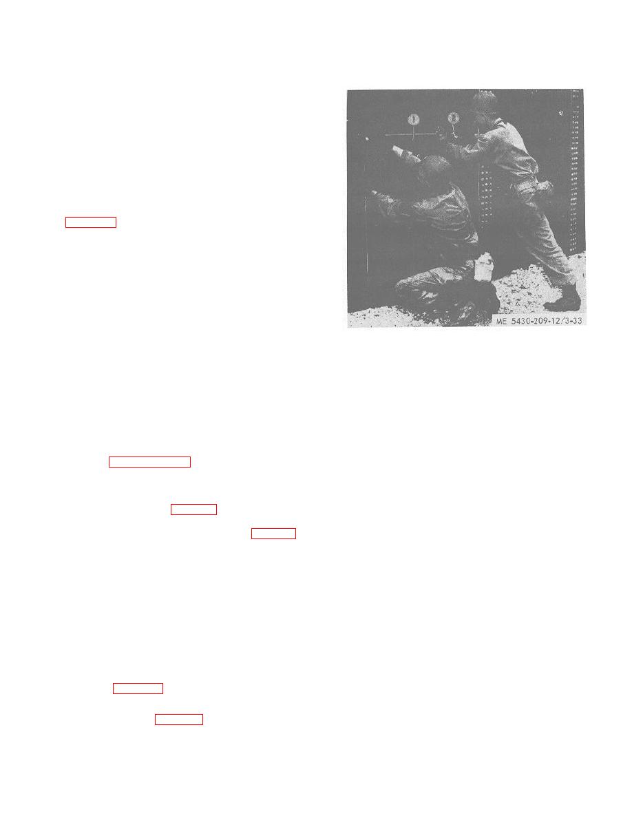
1. CLEANOUT COVER
leaks more than 1/8 inch in 24 hours must be emptied
2. NUT
and inspected for bottom leaks. Repair leaks in a (4)
above.
Figure 3-33. Placing the cleanout cover
3-27. Cleanout Cover
(10,000-barrel capacity tank).
a. General. The cleanout cover is a flat,
rectangular, steel plate drilled and formed to provide a
(4) Install washers, cup side down, over all
liquid-tight cover over the opening of the cleanout stave.
seam bolts. Install nuts, rounded face down, on all bolts.
The bottom edge of the plate is flanged. Two steel
Tighten bolts uniformly around the cover to maintain a
handles are welded to the outside face of the plate.
leakproof joint.
b. Installation.
3-28. Cleaning the Tank Site
(1) See paragraphs 3-23 through 3-26 prior to
The tank erection crew is responsible for the initial
installation of cleanout cover.
policing of the tank site. Clear out all debris, papers,
(2) Push all bolts blush with gasket in chime
cartons, and any other inflammable material. All tools
at bottom to provide clearance for sliding cover in place.
and erection equipment should be returned to the tank
(3) Install cover (1, fig. 3-33) with flange end
erection tool set. The crew should leave a clean and
resting on chime at bottom of tank. Work bolts (3, fig. 3-
neat installation for the pipeline crew or others.
30) through cover. Temporarily install nuts (2, fig. 3-33)
on a sufficient number of bolts to hold cover in place.
Section VII. IDENTIFICATION OF COMPONENT ITEMS
3-29. General
Code
Manufacturer
79154 Victaulic Co. of America
This section contains a list of component items for the
3100 Hamilton Blvd.
100-barrel capacity tank. This list is furnished for your
South Plainfield, N.J. 07080
convenience in identifying individual components of the
81348 Federal Specifications Promulgated by General
tank. Those items required for reassembly are listed as
Services Administration
components of the reerection kit and grouped at the end
81350 Joint Army-Navy Specifications
of the listing.
3-30. Component Items
Promulgated by Standardization
a. Refer to table 3-1 for the list of component
Division, Directorate of Logistic Services, DSA.
items.
97403 U.S. Army Research and Development
b. The following is a list of Manufacturers Codes
Center, Fort Belvoir, Virginia 22060
(MFG Code) contained in Table 3-1.
3-29
|
|
Privacy Statement - Press Release - Copyright Information. - Contact Us |
