 |
|||
|
|
|||
|
Page Title:
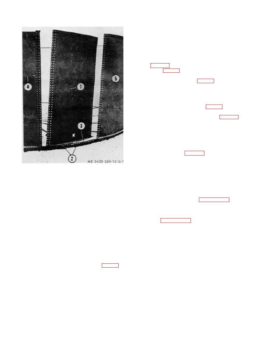
Figure 6-7. Installing last stave |
|
||
| ||||||||||
|
|
 TM 5-5430-209-12
(3) Set stave (1) in position with its left seam outside
the right seam of last intermediate stave (4), and its
right seam inside the left seam of first stave (5). Loosen
bottom chime nuts of staves (4 and 5).
(4) Lift first stave (5) slightly so the bottom
chime of last stave (1) will slip into place. Use drift pins
(3, fig. 3-12) and aline the holes and bolts in staves (1,
4, and 5. fig. 6-7). Install nuts loosely on every sixth or
tenth bolts in each row to hold last stave (1) in place.
(5) Install nuts (3, fig. 6-6) loosely on all chime
bolts (2).
(6) Seat all seam bolts, and install steel washers
and nuts as instructed in d above.
f. Tightening Staves.
(1) Tighten all nuts (3, fig. 6-6) on chime bolts
(2) uniformly.
(2) Use heavy long timber (2, fig. 3-15) as a
lever and short timbers (3) as a fulcrum to raise the tank
bottom, and remove all blocking (1).
(3) Start at the bottom of each stave lap seam
and work toward the top, tightening the nuts evenly in
each row of each seam. Replace stripped nuts or bolts.
(4) Apply sealing compound to inside perimeter
of tank at seams (1, fig. 3-16) formed by the staves and
bottoms (3).
1.
LAST STAVE
6-10. Scaffold
2.
CHIME BOLTS
a. General. Scaffold components are provided in
3.
STRIP GASKET
the tank tool erection set. Before proceeding with
4.
LAST INTERMEDIATE STAVE
further erection of the tank, it is necessary to install
5.
FIRST STAVE
scaffold components around the top chime of the
staves.
Figure 6-7. Installing last stave.
the scaffold.
(2) Install wedge gasket and radii gasket at
chimes on right seam of last stave as instructed in b (3)
6-11. Dressing Top Chime
above.
Refer to paragraph 3-9 and dress the top chime.
Section III. ASSEMBLY AND INSTALLATION OF TANK CENTER
SUPPORT ASSEMBLY
6-12. Assembly of Umbrella-Type Deck Support
(2). Each strut is connected by a strut clip (3) and bolts
a. General. The umbrella-type deck support
(5) to the rafter landing ring (1). Gusset cone (4) is the
center component of the support. It has five plates to
consists of a 1-piece, rafter landing ring (1, fig. 6-8)
which the struts are connected by bolts (6).
fitted on the inside with five equally spaced struts
6-7
|
|
Privacy Statement - Press Release - Copyright Information. - Contact Us |
