 |
|||
|
|
|||
|
Page Title:
Section III. TERRESTRIAL TELESCOPES |
|
||
| ||||||||||
|
|
 TM 9-258
5-7.
Magnification of Telescopes.
a. Computation of power in an astronomical
telescope is done by dividing the focal length of the
objective by the focal length of the eyepiece. This is true
only when the virtual image is at infinity or when
emergent rays from point object are parallel. If the
image is moved to the near point of the eye (10 inches),
it increases slightly in size.
b. This equation cannot be applied to all
terrestrial systems using lens erecting systems since
such erecting systems can, and usually do, contribute to
the power. It can be applied to any terrestrial system
using a prism erecting system.
Figure 5-8. Reflecting astronomical telescope.
Section III. TERRESTRIAL TELESCOPES
the eyepiece to erect the image as in figure 5-9. A prism
5-8.
General. This instrument gets its name from the
erecting system is placed between the objective and its
Latin term "terra" which means earth and is basically
focal point, but a lens erecting system requires
useful for looking at objects as they actually appear to us
repositioning of objective and eyepiece so that erectors
on earth. Any astronomical telescope can be converted
are between objective focal point and first principal focus
into a terrestrial telescope by inserting an erecting
of eyepiece.
system. either lens or prism, between the objective and
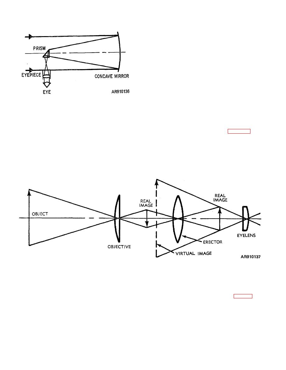
Figure 5-9. Terrestrial telescope--simple form.
erecting system. The first lens may be placed one focal
5-9.
Lens Erecting Systems.
length behind the image formed by the objective and the
a. Location. A lens erecting system is placed
second spaced a distance equal to the focal length of
between the focal plane of the objective and the front
either to minimize spherical aberrations (fig 5-10).
focal plane of the eyepiece. In practice, to minimize
aberrations, two or more lenses usually comprises a lens
5-4
|
|
Privacy Statement - Press Release - Copyright Information. - Contact Us |
