 |
|||
|
|
|||
|
Page Title:
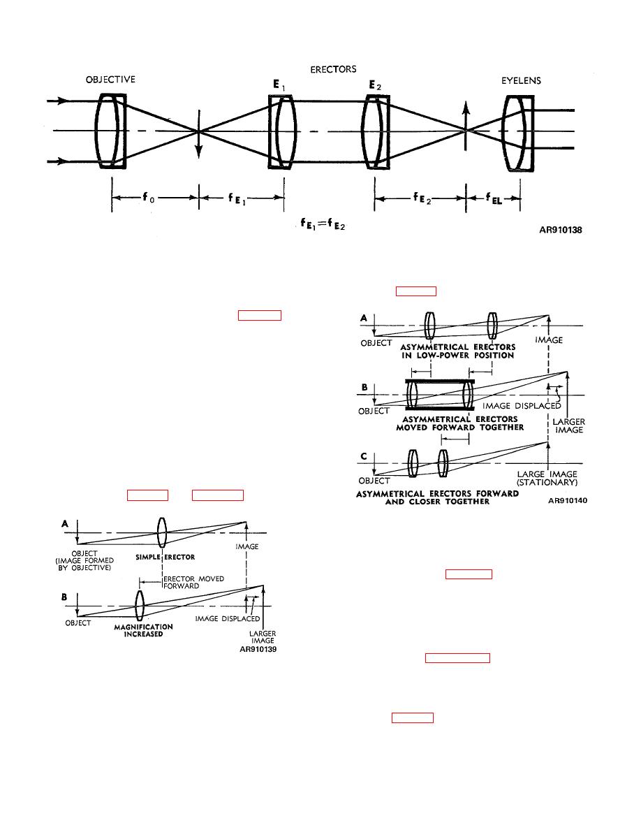
Figure 5-10. Symmetrical erectors. |
|
||
| ||||||||||
|
|
 TM 9-258
Figure 5-10. Symmetrical erectors.
b. Symmetrical. A true symmetrical erecting
separation between the elements in the erecting system
(A, B, and C fig 5-12).
system is composed of symmetrical lenses so positioned
that the object (real image formed by the objective) and
image distances are symmetrical or equal (fig 5-10). In
other words, the image formed by the objective is at the
focal point of the front erector and the rays between the
two erectors are parallel. Therefore, spacing between
erectors is not critical and does not affect magnification
as the magnification in such a system (always-1)
indicates an inverted image of same size as object
regardless of lens separation.
c. Variable
Magnification.
Variable
magnification erecting systems used in variable power
telescopes may provide (in the high-power position) from
two to three times the power produced in the low-power
position depending on the design. In the simplest lens
erecting system (a single lens), magnification can be
shown to be a function of object distance and image
distance (A and B, fig 5-11, and para 2-24e). The same
is true if a combination of lenses (usually two) is used.
Figure 5-12. Asymmetrical erectors.
(2) When magnification is increased by
shifting erectors forward, the image position shifts toward
the eyepiece as in B, fig 5-12. A change in distance
then, between the asymmetrical elements in this forward
position, further affects magnification and image
distance. A decrease in the distance between the
elements, i.e., moving the second lens nearer the first,
lessens the increase in magnification slightly but more
important decreases the shift in the resulting image
position as in C, figure 5-12. By design, the image
position can be the same for any of the possible
Figure 5-11. Simple erector.
magnifications. In this case, the separation between
erector elements is always such that the image position
(1) Magnification of an erecting system
remains fixed for any magnification and the eyepiece can
composed of a combination of asymmetrical lenses
be fixed (C, fig 5-12).
(lenses of different focal lengths) can be varied either by
(3) If magnification is increased, either by
varying the distance of the erecting system from its
shifting the erector system forward as a complete
object (image formed by objective) or by varying the
5-5
|
|
Privacy Statement - Press Release - Copyright Information. - Contact Us |
