 |
|||
|
|
|||
|
Page Title:
Section V. WIRING HARNESS AND CABLE REPAIR |
|
||
| ||||||||||
|
|
 TM
9-2350-238-20-2
Section V. WIRING HARNESS AND CABLE REPAIR
2-11.
G E N E R A L . This section contains instructions on repair of wiring harnesses and cables
(leads). Repair of wiring harnesses and cables consists of replacement of defective connectors,
shells and terminals or taping cut or worn insulation and exposed wire conductors. Pages 2-66
thru 2-72 show exploded views of typical harness and cable connectors used on the vehicle,
and give procedures for disassembly and assembly
of
connectors.
When
is
required,
procedures in TB SIG 222 must be followed.
NOTE
Label
cables
on
multiple
during
disassembly
to
insure
proper
order
during
reassembly.
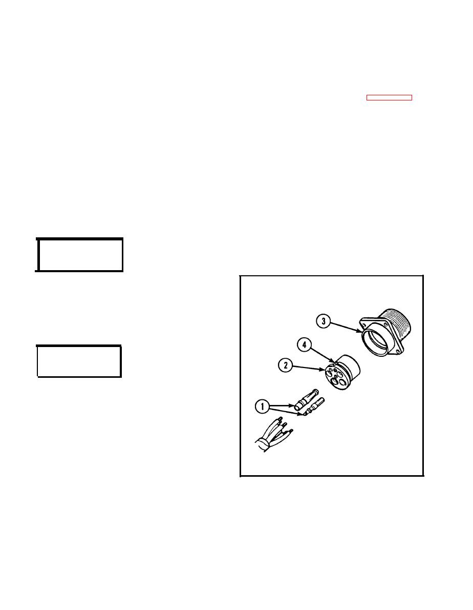
2-12. TYPICAL FEMALE-TYPE
PANEL
MOUNTING RECEPTACLE.
DISASSEMBLY
1 Drive socket contacts (1) out through
rear of insert (2) with pin extractor.
2 Unsolder
cable
leads
from
solder
wells
on
socket
contacts
(1).
3 Slide insert out through rear of shell
assembly (3).
REASSEMBLY
1
Strip cable insulation equal to depth of
solder
wells
of
socket
contacts
(1).
2
Insert cable leads into solder wells of
socket
contacts
(1)
and
Push insert (2) into shell assembly (3)
3
from rear until seated. Groove (4) in in-
sert must be alined with guide in shell
assembly (3) to ensure proper fit.
4
Push socket contacts (1) into insert (2)
from rear until seated.
|
|
Privacy Statement - Press Release - Copyright Information. - Contact Us |