 |
|||
|
|
|||
|
Page Title:
BOOM AND WINCH INSTALLATION (Cont) |
|
||
| ||||||||||
|
|
 TM
9-2350-238-20-2
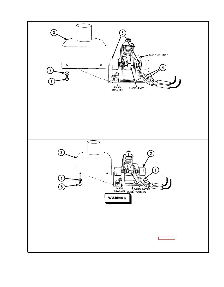
(2) Level wind traverses cab in only one direction.
Remove three screws (1), three washers (2), and cover (3) for access to
Step 1.
sensing switches. Disconnect leads 480 (4) from sensing switch (5) of the
inoperative traversing circuit. Connect multimeter to sensing switch. Press
sensing switch to close. If multimeter indicates continuity, go to step 2. If
multimeter indicates infinity, notify direct support maintenance for replace-
ment of sensing switches. Connect leads.
Make sure MASTER switch is OFF before repairing electrical com-
ponents. Failure to observe this warning could result in injury to
personnel.
Place
red
probe
in
lead
480
(1).
Ground
black
probe.
Set
MASTER
switch
Step 2.
ON. Set LEVEL WIND switch ON. If multimeter indicates about 24 volts, go
to step 3. If multimeter indicates no voltage, repair lead 480 between sens-
ing switch (2) and LEVEL WIND switch, refer to page 2-66. Set MASTER
switch
OFF.
Set
LEVEL
WIND
switch
OFF.
Connect
leads.
Install
cover
(3)
with
three
washers
(4)
and
three
screws
(5).
|
|
Privacy Statement - Press Release - Copyright Information. - Contact Us |
