 |
|||
|
|
|||
|
Page Title:
GENERATOR CHARGING CIRCUIT. (Cont) |
|
||
| ||||||||||
|
|
 TM 9-2350-238-20-1
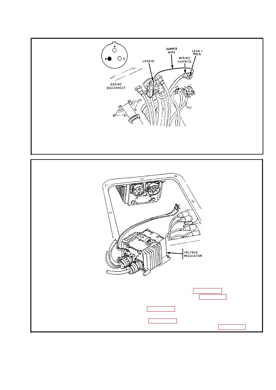
Step 13. Disconnect electrical lead (lead 82) and wiring harness at engine
disconnect. Place insulated jumper wire to pin B (lead 1). Set MASTER
switch ON. Strike jumper wire to socket (lead 82). Connect leads and go
back to step 12.
generator-regulator charging circuit test. Refer to page 2-138. If
generator-regulator charging circuit operates properly, permanently replace
voltage regulator. Refer to page 2-557. If generator-regulator charging
circuit does not operate properly, remove temporary voltage regulator and
replace generator. Refer to page 2-552. After replacing generator,
perform generator-regulator charging circuit test. Refer to page 2-138.
2-147
|
|
Privacy Statement - Press Release - Copyright Information. - Contact Us |