 |
|||
|
|
|||
|
Page Title:
GENERATOR-REGULATOR CHARGING CIRCUIT TEST. |
|
||
| ||||||||||
|
|
 TM 9-2350-238-20-1
2-12. ELECTRICAL CIRCUIT TROUBLESHOOTING (CONT).
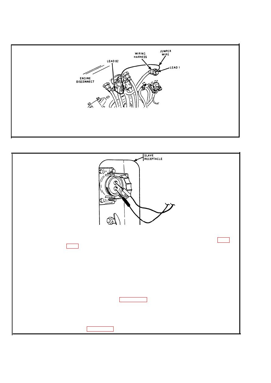
Disconnect electrical lead (lead 82) and wiring harness at engine
Step 9.
disconnect. Place insulated jumper wire to pin B (lead 1). Set MASTER
switch ON. Strike jumper wire to socket (lead 82). Connect leads and go
back to step 8. Set MASTER switch OFF.
I. GENERATOR-REGULATOR CHARGING CIRCUIT TEST.
Check voltage at slave receptacle terminals with engine running.
Step 1.
Multimeter should indicate about 27 volts. If multimeter indicates less than
22 volts, stop engine. Troubleshoot battery power circuit. Refer to page
With engine running at 1000 to 1200 rpm, set vehicular light switch to SER
Step 2.
DRIVE. Press headlight dimmer switch until HI BEAM IND light is on.
Check voltage at slave receptacle with engine running. Multimeter reading
Step 3.
should increase 1 to 3 volts above reading in step 1. If voltage increases
above 29 volts, stop engine and troubleshoot generator output circuit for
overcharging. Refer to page 2-133.
If voltage increases momentarily and then drops back to first reading,
Step 4.
--
generator-regulator charging circuit is not operating properly. Stop engine,
turn vehicular light switch OFF, and troubleshoot generator charging circuit.
Refer to page 2-139.
2-138
|
|
Privacy Statement - Press Release - Copyright Information. - Contact Us |
