 |
|||
|
|
|||
|
|
|||
| ||||||||||
|
|
 TM 9-2330-202-14&P
4-35.
SERVICE BRAKE MAINTENANCE (CONTINUED).
3.
Install two brakeshoes (14 and 15), pins (22), and springs (21) on backing plate (6). Install two retain-
ers (20), spring (24), and strut (23) on backing plate (6).
4.
Turn in adjusting screw (19) fully. Install adjusting screw (19) and spring (18) between two brake-
shoes (14 and 15).
5.
Install plate (17) on anchor pin (16).
6.
Install two springs (13) on anchor pin (16)
and brakeshoes (14 and 15).
e.
INSTALLATION
1.
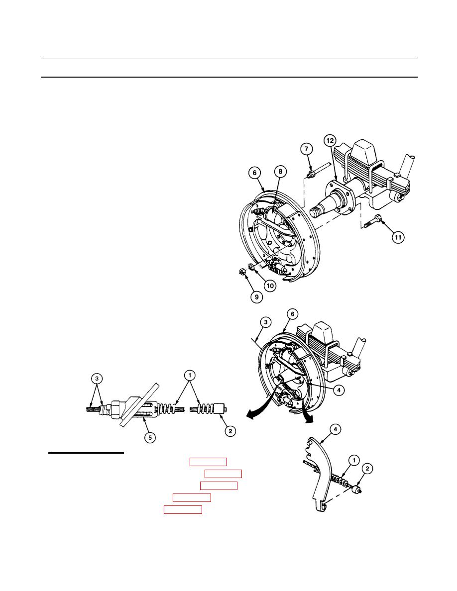
Install backing plate (6) and service brake
assembly on axle (12) with five capscrews
(11), new lockwashers (10), and nuts (9).
2.
Connect hydraulic tube assembly (7) to
wheel cylinder (8) at backing plate (6).
3.
Feed handbrake cable assembly (3)
through backing plate (6) and position at
lever (4). Make sure lock tangs (5) are
spread and hold handbrake cable assembly
(3) securely in backing plate (6).
4.
Pull spring (1) away from swaged sleeve
(2), and hook swaged sleeve (1) to lever
(4).
FOLLOW-ON TASKS:
Install hub and brakedrum (para 4-43).
Install wheel and tire assembly (para 4-44).
Bleed hydraulic brake system (para 4-41).
Adjust service brakes (para 4-36).
Adjust handbrakes (para 4-34).
|
|
Privacy Statement - Press Release - Copyright Information. - Contact Us |