 |
|||
|
|
|||
|
Page Title:
Voltage Regulator Adjustment cont'd |
|
||
| ||||||||||
|
|
 TM 9-2320-360-20-2
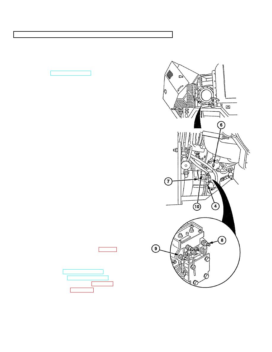
7-2. ALTERNATOR TEST/VOLTAGE REGULATOR ADJUSTMENT (CONT)
(8) Remove plastic screw (6) from access hole in
cover (7).
(9) Connect voltmeter leads across positive (+)
terminal (8) and negative (-) terminal (9).
(10) Start and operate engine at idle with aid of
assistant (TM 9-2320-360-10).
(11) Insert small screwdriver in access hole cover.
CAUTION
Do not force adjusting screw past
stops at either end of range.
Damage to voltage regulator may
result.
NOTE
Turn adjusting screw clockwise to
increase voltage, counterclockwise
to decrease voltage.
Replace alternator
if
28.02
volts
cannot be obtained.
(12) Turn adjusting screw (10) until voltage of 28.02
is achieved.
(13) Install plastic screw (6) in access hole of cover
(7).
(14) Disconnect voltmeter test leads from negative (-)
terminal (9) and positive (+) terminal (8).
NOTE
If voltage at batteries is not within
specifications, after voltage regulator
adjustment, refer to Electrical System
Troubleshooting.
(15) Test alternator output at batteries (para 7-2a).
d. Follow-On Maintenance
(1)
Shut off engine (TM 9-2320-360-10).
(2)
Close battery box (TM 9-2320-360-10).
(3)
Install alternator access panel (para 16-2).
(4)
Install inner fender (para 16-34).
7-4.2 Change 1
|
|
Privacy Statement - Press Release - Copyright Information. - Contact Us |
|
|
Integrated Publishing, Inc. - A (SDVOSB) Service Disabled Veteran Owned Small Business
|

