 |
|||
|
|
|||
|
|
|||
| ||||||||||
|
|
 TM 9-2320-360-20-2
NOTE
Batteries should be at least 95% charged.
Specific gravity readings should be
greater than 1.270.
b. Voltage Regulator Adjustment
WARNING
Use extreme care when measuring voltage while engine is running. Rotating fan
blade and hot engine parts may cause injury.
CAUTION
Electrical accessories should be in off position for adjustment to be correct.
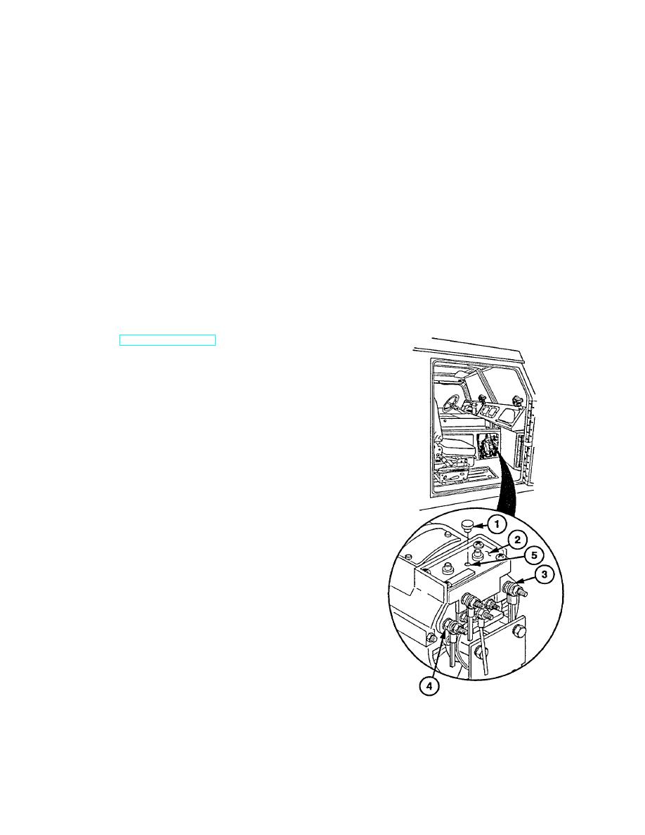
(1) Remove plastic cap (1) from access hole in
cover (2).
(2) Connect voltmeter leads across positive (+)
terminal (3) and negative (-) terminal (4).
(3) Start and operate engine at idle with aid of
assistant (TM 9-2320-360-10).
(4) Insert small screwdriver in access hole of cover.
CAUTION
Do not force adjusting screw past
stops at either end of range. Damage
to voltage regulator may result.
NOTE
Turn adjusting screw clockwise to increase
voltage, counterclockwise to decrease
voltage.
Replace alternator
if
14.05
volts
cannot be obtained.
(5) Turn adjusting screw (5) until voltage of 14.05
vdc is obtained.
(6) Install plastic cap (1) in access hole of cover (2).
(7) Disconnect voltmeter test leads from negative (-)
terminal (4) and positive (+) terminal (3).
Change 1 7-4.1
|
|
Privacy Statement - Press Release - Copyright Information. - Contact Us |
|
|
Integrated Publishing, Inc. - A (SDVOSB) Service Disabled Veteran Owned Small Business
|

