 |
|||
|
|
|||
|
Page Title:
Section II. MAINTENANCE PROCEDURES |
|
||
| ||||||||||
|
|
 TM 9-2320-360-20-2
This chapter contains instructions for adjustment, replacement, and repair of electrical system components at the Unit
maintenance level. Some parts must be removed before the electrical system components can be accessed. They are
referenced to other paragraphs of this manual or TM 9-2320-360-10.
Section II. MAINTENANCE PROCEDURES
7-2. ALTERNATOR TEST/VOLTAGE REGULATOR ADJUSTMENT
This task covers:
a. Alternator Test
c.
Follow-On Maintenance
b. Voltage Regulator Adjustment
INITIAL SETUP
Equipment Conditions
Tools and Special Tools
Battery Box Open (TM 9-2320-360-10)
Tool Kit, Genl Mech (Item 54, Appendix F)
Alternator access panel removed
Multimeter (Item 20, Appendix F)
Inner Fender Removed (left side only)
Personnel Required
Two
Engine running (TM 9-2320-360-10).
a. Alternator Test
WARNING
Remove rings, bracelets, watches,
necklaces, and any other jewelry
before working around HET Tractor.
Jewelry can catch on equipment and
cause
Injury
or
short
across
electrical circuit and cause severe
burns or electrical shock.
NOTE
Batteries should be at least 95%
charged. Specific gravity should be
greater than 1.270.
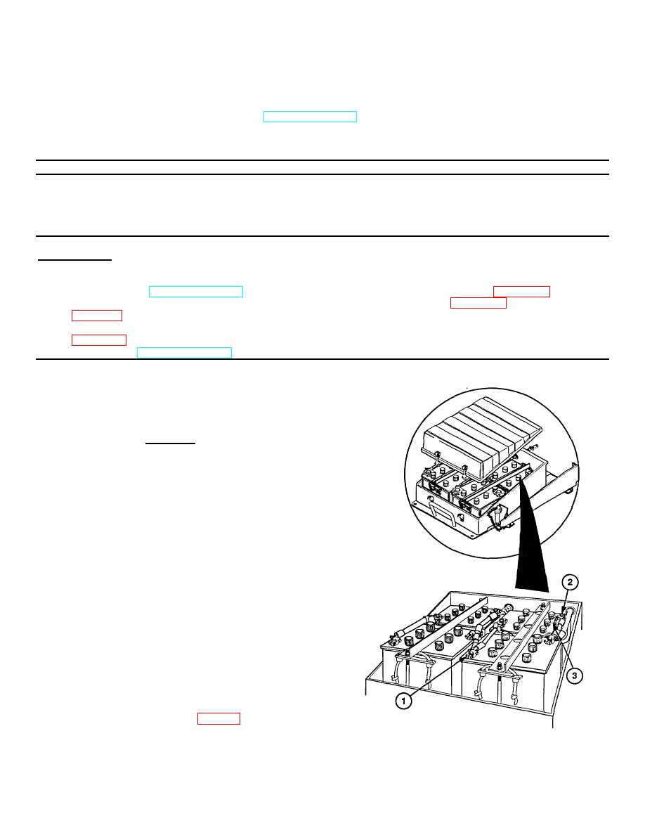
(1) Check
battery
specific
gravity
(para 2-12, Item 17).
(2) Connect digital multimeter to positive (+)
terminal (1) and negative (-) terminal (2) of
batteries (3). Record voltage displayed on
(3) If voltage is not 13.90-14.10 volts, adjust
voltage regulator(s) (para 7-2b).
Change 3 7-3
|
|
Privacy Statement - Press Release - Copyright Information. - Contact Us |