 |
|||
|
|
|||
|
Page Title:
STOPLIGHT DOES NOT WORK WHEN TRACTOR BRAKES ARE APPLIED - CONTINUED |
|
||
| ||||||||||
|
|
 TM 9-2320-270-20-1
TROUBLESHOOTING - CONTINUED
MALFUNCTION
TEST OR INSPECTION
CORRECTIVE ACTION
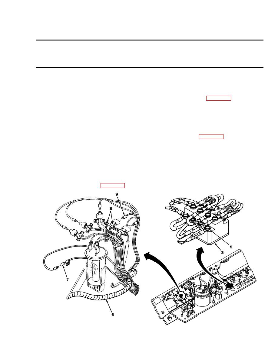
Step 13.
Put blackout switch (3) switch lever in LIGHTS position. Using multimeter
set at 30 vdc, put red probe on wire no. 294 (5), and black probe to good
ground. While assistant applies brakes, take reading, and release brakes.
If meter reads no voltage, replace blackout switch (page 4-298).
Step 14.
At connector harness (6) for directional signal control, disconnect wire no.
294 (7) from red wire. Using multimeter set at 30 vdc, put red probe on wire no.
294 (7) and black probe to good ground. While assistant applies brakes, take
reading, and release brakes.
If meter reads no voltage, close instrument panel (page 4-244) and no-
tify direct support maintenance.
Step 15.
Plug wire 294 into connector. At to connector harness (6) for directional signal
control, disconnect wires no. 003, A and B (8) from orange wire (9). Using
multimeter set at 30 vdc, put red probe on orange wire and black probe to good
ground. While assistant applies brakes, take reading, and release brakes.
If meter reads no voltage, replace directional signal control
TA239680
3-93
|
|
Privacy Statement - Press Release - Copyright Information. - Contact Us |
