 |
|||
|
|
|||
|
Page Title:
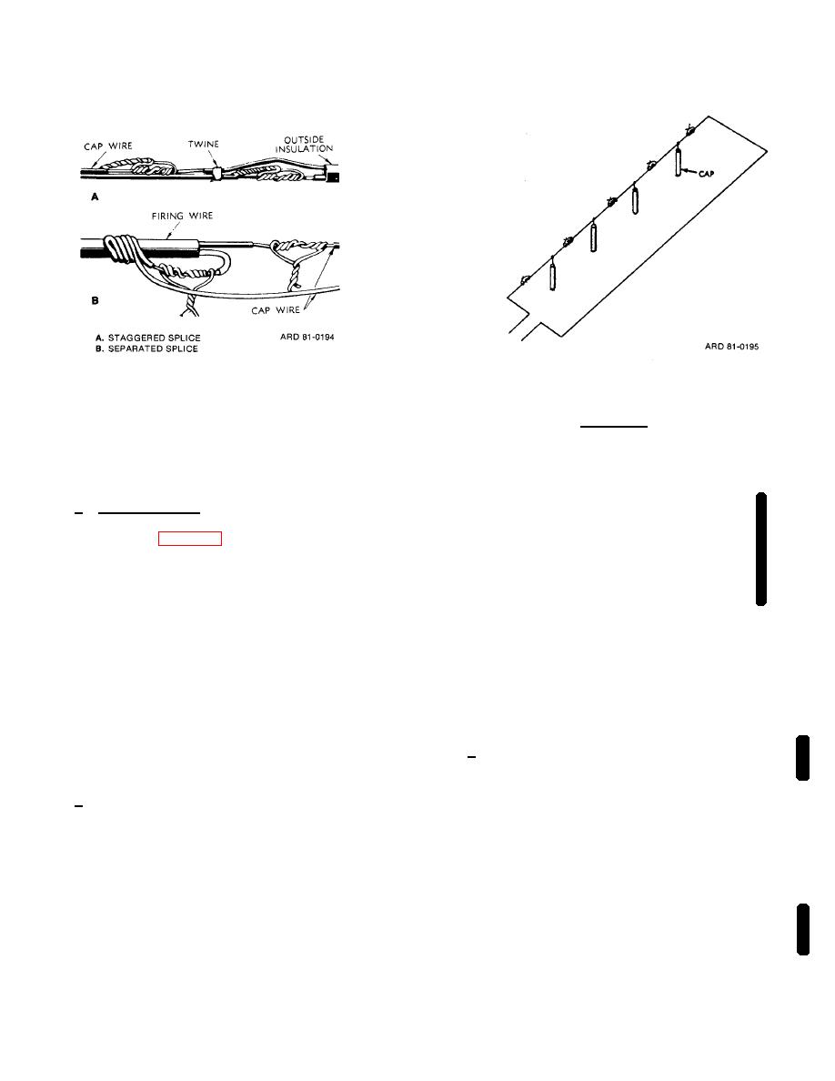
Figure 5-10. Splicing two pairs of wires |
|
||
| ||||||||||
|
|
 TM 9-1300-277
Figure 5-10. Splicing two pairs of wires.
Figure 5-11. Common series circuit.
WARNING
(4) Circuit splices, not taped or insulated,
INDUCED CURRENTS FROM RADIO
.
should not lie on moist ground. Splices should be
FREQUENCY (RF) SOURCES CAN
supported on rocks, blocks, or sticks so that only
INITIATE
BLASTING
CAPS
insulated portions of wires touch ground.
CONNECTED TO LONG LEAD OF
WIRE.
BEFORE CONNECTING
d. Common Series. This is used for connecting
ELECTRIC BLASTING CAPS TO THE
two or more charges fired electrically by a single
FIRING WIRES, THE BLASTING
blasting machine (fig. 5-11). A common series circuit is
CIRCUIT MUST BE TESTED FOR
prepared by connecting one blasting cap lead wire from
THE PRESENCE OF EXTRANEOUS
the first charge to one lead wire in the second charge
ELECTRICITY AND RF ENERGY.
and so on until only two end wires are free. Connecting
wires (usually annunciator wire) are used when the
FACE AWAY FROM CAPS WHEN
.
distance between blasting caps is greater than the
length of the usual cap lead wires.
CIRCUIT
IS
COMPLETED
TO
MINIMIZE FACE INJURIES FROM
5-10. PRIMING AND TESTING FIRING CIRCUIT
ACCIDENTAL INITIATION. IF AT ALL
POSSIBLE,
MAINTAIN
COVER
NOTE
BETWEEN BLASTING CAPS AND
At firing position, keep free ends of
TESTING PERSONNEL.
firing wire twisted together and
grounded until ready to connect to
b. Check for presence of RF energy and/ or
galvanometer or to blasting machine.
extraneous electricity as follows:
a. Splice one of the free cap lead wires to a firing
(1) Arrange a dummy test circuit, essentially
wire conductor.
the same as the actual blasting circuit except that a No.
47 radio pilot lamp of known good quality inserted in
place of the blasting cap shall be used without applying
electric current to the circuit. Any glow of the radio pilot
lamp, viewed in the darkness, is to be construed as
evidence of the presence of possible dangerous
amounts of RF energy, and/or extraneous electricity;
blasting operations in such areas must be performed
with nonelectric blasting caps and safety fuse.
Change 2
5-10
|
|
Privacy Statement - Press Release - Copyright Information. - Contact Us |