 |
|||
|
|
|||
|
Page Title:
CONNECTING/SPLICING ELECTRIC WIRES |
|
||
| ||||||||||
|
|
 TM 9-1300-277
5-9. CONNECTING/SPLICING ELECTRIC WIRES
WARNING
THE FIRIDG WIRE WILL BE
.
SHUNTED AND GROUNDED AT THE
INITIATING
PCINT
PRIOR
TO
CONNECTION OF THE BLASTINC
CAP.
THE
.
PERSON
MAKING
THE
CONNECTION WILL WORK AS FAR
FROM BLASTING CAP AS CAP LEAD
WIRES WILL ALLOW WITH BACK
TURNED TO TIE CAP TO MINIMIZE
INJURY IN CASE OF PREMAT'TURE
DETONATION.
NOTE
Other methods of splicing may be
used as long as electrical continuity
is maintained.
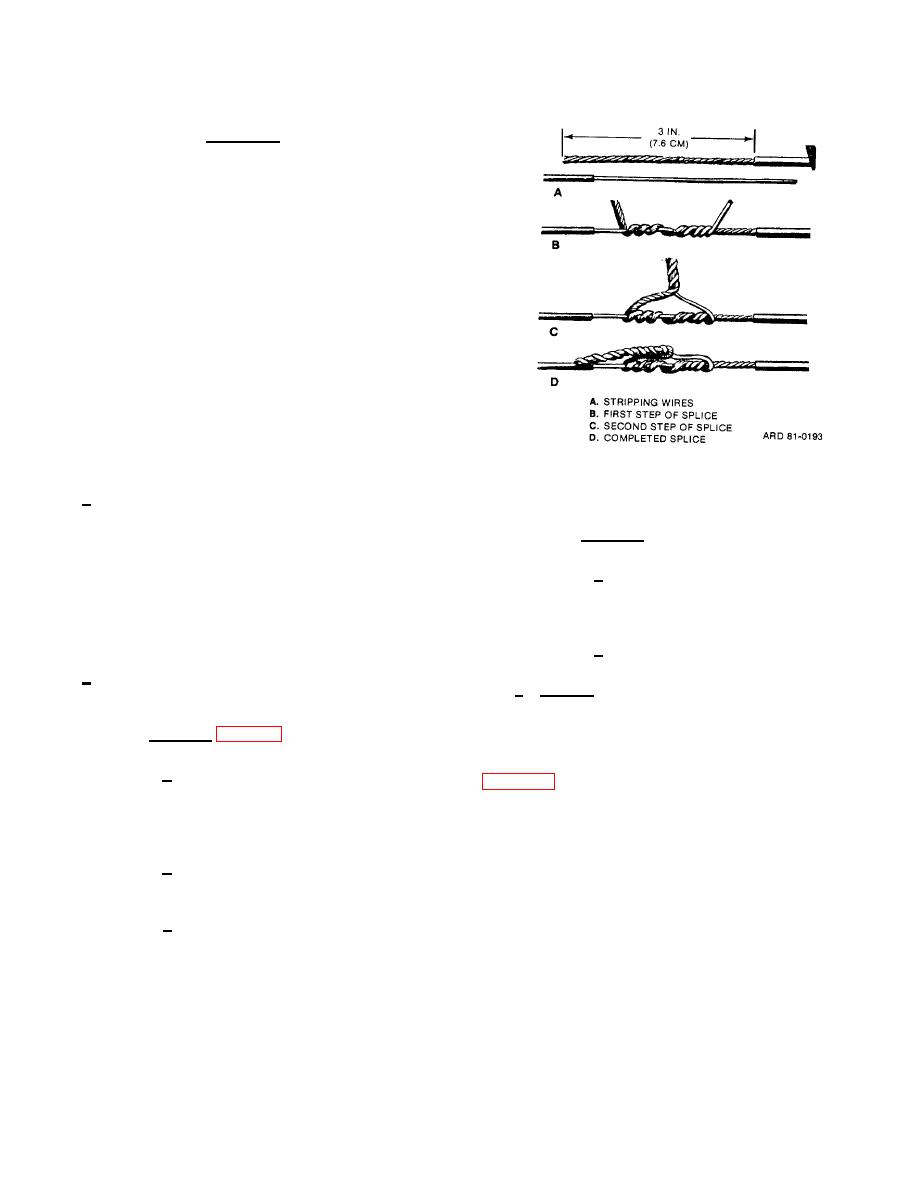
Figure 5-9. Wire splicing.
a. Insulated wires, before splicing, must have the
insulating material stripped from the ends. Expose
about e centimeters (3 inches) of bare wire (fig. 5-9.
(2) Method 2.
detail A), and remove any foreign matter such as
enamel by carefully scraping the wire with the back of a
(a) Place the two wires to be
knife blade or other suitable tools. The wires should not
connected, side by side, with free ends pointing in same
be nicked, cut, or weakened when the wires are bared,
direction and wind them together by twisting.
and multiple strand wires should be twisted lightly after
scraping.
(b) Tape to ensure complete insulation.
b. Connecting may be accomplished by any one of
c. Splicing. The following precautions will prevent
the following methods.
a short circuit.
(1) Method 1 (fig. 5-9).
(1) If pairs of wires are spliced, stagger the
two separate splices and tie with twine or tape (detail A,
(a) Point free ends in opposite
directions (detail A), join with a few tight twists around
each other, and bend remaining ends up, away from
(2) An alternate method is shown in detail B.
joint (detail B).
Splices are separated, not staggered, in the alternate
method.
(b) Twist these ends to form a pigtail
(detail C), which is at right angles to connected wires.
(3) Whenever possible, insulate splices from
ground or other conductors by wrapping them with
(c) Push pigtail to one side to lie along
friction tape or other electric insulating tape.
one of the wires (detail D). Tape connection to ensure
complete insulation.
5-9
|
|
Privacy Statement - Press Release - Copyright Information. - Contact Us |
