 |
|||
|
|
|||
|
|
|||
| ||||||||||
|
|
 TM 9-1300-277
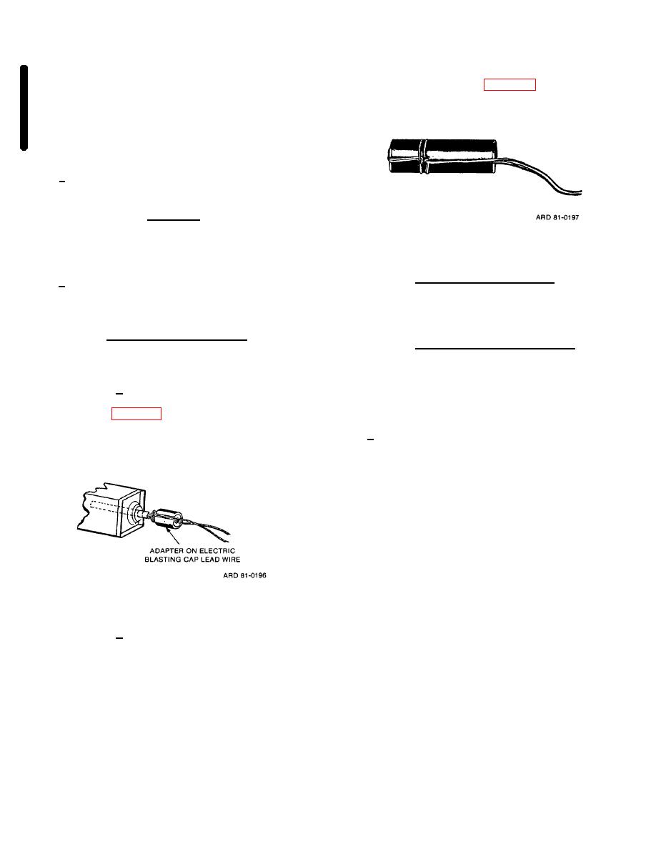
cap is inserted in well and cap wires are tied around the
(2) The duPont Blaster's Multimeter Model
charge by two-half hitches (fig. 5-13). As an alternate
101 may be substituted for the No. 47 radio pilot lamp
method, use tape to secure blasting cap to prevent
when testing for extraneous electricity, but will not
blasting cap withdrawal.
detect RF energy. Distances prescribed in TM 9-1300-
206 or DARCOMR 385-100 should be used as a guide
in the selection of sites for electric blasting operations in
the vicinity of RF energy transmitters.
c. Splice free end of cap lead wire to free end of
firing wire.
WARNING
NEVER TRY TO FORCE A CAP INTO
CAP WELL THAT IS TOO SMALL TO
Figure 5-13. Two half hitches.
ADMIT THE CAP EASILY.
(2) M1 chain demolition block. Tape an
d. Priming will be accomplished by one of the
electric blasting cap to one of the free ends of the
following methods, determined by the type of explosive
detonating cord chain. The explosive end of the cap will
used.
point toward the chain demolition block.
(1) Charges having cap wells.
Charges
(3) Plastic explosives composition C. Plastic
having cap wells (threaded or unthreaded) may be
explosive charges not having cap wells will be primed
primed as follows:
by forming a cap well in the charge using the pointed leg
of the M2 crimper and inserting blasting cap into the
(a) Use of blasting cap with priming
formed cap wells. Composition C-4 should then be
adapter. The cap lead wires are passed through the slot
molded around the blasting cap.
of the adapter (fig. 5-12) and blasting cap is pulled into
place in adapter. The cap and adapter are then inserted
e. The firing circuit will be tested as follows (fig. 5-
into cap well of the demolition charge and adapter is
14).
screwed into place.
(1) Ensure that all joints and bare sections
are separated and placed out of contact with the ground
and all other conductors.
(2) Hold one end of firing wire to one post of
galvanometer and touch other end to other post.
(3) Circuit is complete if needle moves
across scale. The amount of deflection of needle
depends on length and type of firing wire and number of
Figure 5-12. Priming adapter.
blasting caps in the firing circuit. If test indicates a
break or high resistance, shunt the wires and then repair
wire or connections. Caps will be retested if necessary.
(b) Use of blasting cap without priming
adapter. When priming adapters are not available or
demolition charge does not have a threaded cap well,
Change 2
5-11
|
|
Privacy Statement - Press Release - Copyright Information. - Contact Us |