 |
|||
|
|
|||
|
Page Title:
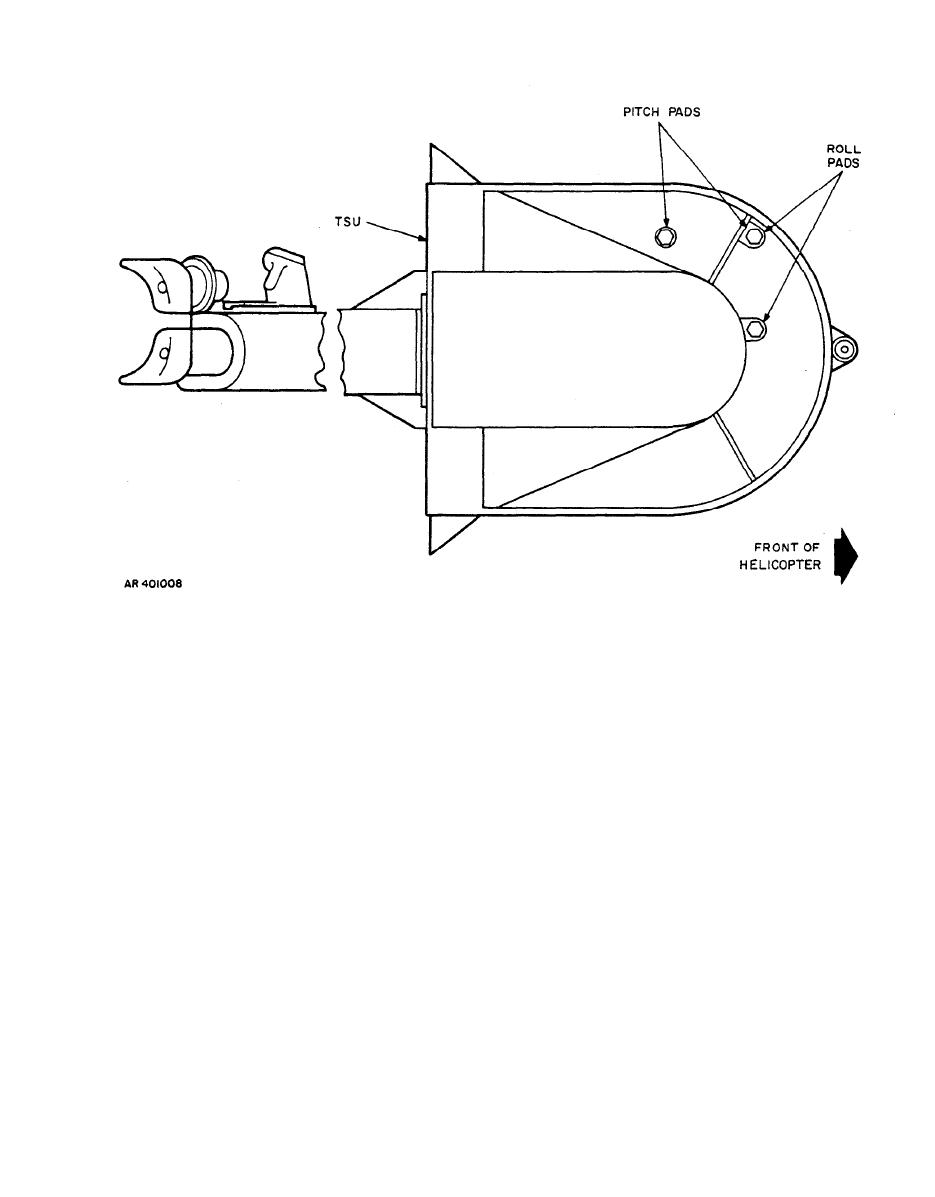
Figure 4-3. Top view of TSU pitch and roll pads |
|
||
| ||||||||||
|
|
 TM 9-1270-212-14&P
n. Check that all target assemblies are plumb to the TSU
j. Place the right target assembly (foldout FO-11, sheet
boresight device plane within 1/2 degree (8.9 mils) as
3) to the right side of the helicopter and at a distance of
defined by the alignment pads. This is done by placing a
1000 6 inches (83 feet 4 inches, 6 inches) from the
gunner's quadrant on the TSU boresight device, leveling the
reference point marked on the ground, keeping the viewing
bubble, and then transferring the quadrant to the target.
face of the target assembly parallel with the imaginary
For the left and right targets, the gunner's quadrant will be
centerline of the helicopter as much as possible on initial
placed on the TSU boresight device so that it is parallel to
placement.
the centerline of the helicopter. For the forward target, the
gunner's quadrant will be placed on the TSU boresight
k. Sight through the borescope at the TSU borescope
device so that it is perpendicular to the centerline of the
device target.
helicopter. When transferring the gunner's quadrant from
the TSU boresight device to the target, maintain the same
1. With the assistance of a second person to move the
orientation of the quadrant.
right target assembly in azimuth and elevation as directed
by the person viewing the target through the borescope,
o. Once all three target assemblies have been initially
adjust the right target so that the intersection of the TSU
boresight device target is coincident with the intersection of
placed and aligned, insert the borescope in each of the three
the crosshairs of the borescope reticle.
holes in the TSU boresight device again, to verify that each
target is properly aligned in azimuth and elevation as
m. Insert the borescope in the left tapered hole of the
specified in the preceding procedures. These conditions
TSU boresight device. Place the left target (foldout FO-11,
locate the left and right target assemblies at 90 degrees
sheet 1) to the left of the helicopter by performing
from the center target assembly and align the center target
procedures parallel to those in i through l.
assembly with the 0-degree azimuth position of the TSU.
|
|
Privacy Statement - Press Release - Copyright Information. - Contact Us |
