 |
|||
|
|
|||
|
Page Title:
Section II. ALIGNMENT AND BORESIGHTING PROCEDURES |
|
||
| ||||||||||
|
|
 TM 9-1270-212-14&P
Section II. ALIGNMENT AND BORESIGHTING PROCEDURES
-
4-3. Scope.
c. Remove the fairing covering the TSU mounting pad
located on the TSU upper turret support assembly.
The procedures in this section establish the requirements
d. Place the TSU boresight device onto the TSU
for aligning and boresighting the helmet-directed fire
control sub system (HSS) to the telescopic sight unit (TSU)
reference pads (fig. 4-3) and lock into place with the screw
for XM128, AH-l S (Mod) and XM136, AH-l S .
fastener.
For boresighting procedures for XM 136, AH-1S
NOTE
, refer to TM9-1090-206-30, Aviation Inter-
and
mediate Maintenance Manual for Armament Subsystem,
Do not remove or adjust the factory-set TSU
Helicopter: 20-mm Automtitic Gun, XM97E1/E2.
reference pads.
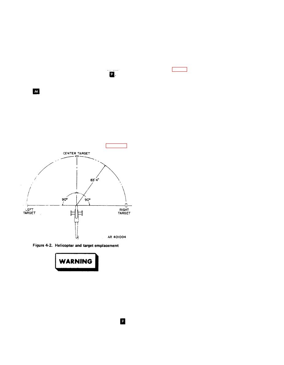
e. Using a steel tape, measure 1000 6 inches (83 feet 4
inches, 6 inches) in front of the TSU from the plumb
Prepare for the system alignment by performing the
mark directly below the pivot point of the TSU.
procedures listed in the following paragraphs:
NOTE
a. Position the fairly leveled helicopter in an area that
will accommodate the equipment, as shown in figure 4-2.
Technicians should now assume the gunner's
and pilot's positions and remain there for the
remainder of the alignment and boresighting.
Do not lean on or stand on the aircraft skids
during this operation.
f.
Place the center target assembly (foldout FO-11
sheet 3) forward of the helicopter and at a distance of 1000
6 inches (83 feet 4 inches, 6 inches), keeping the target
perpendicular to the imaginary centerline of the helicopter
as much as possible on initial placement.
g. Place the borescope in the center hole of the TSU
boresight device. Sight through the borescope at the TSU
boresight device target.
h. With the assistance of a second person to move the
center target assembly in azimuth and elevation as directed
by the person viewing the target through the borescope,
adjust the center target assembly so that the intersection of
the TSU boresight device target is coincident with the
intersection of the crosshairs within the small circle of the
borescope reticle.
NOTE
Unload the turret weapon subsystem and all
wing stores weaponry to prevent injury to per-
If there is insufficient height adjustment in the
sonnel through accidental firing of a weapon.
targets, the helicopter or the target assemblies
may need to be shimmed in order to align the
h Verity that all the components of the HSS, except
target assemblies properly.
the helmet sight assemblies, and the associated components
and panels are installed and are functionally operational.
i. Insert the borescope in the right tapered hole of the
Connect the shorting plug to the connector for the helmet
TSU boresight device. The borescope should be either,
sight assembly in the gunner's compartment (17P1
or
vertical or horizontal for best sighting results.
P247, AH-IS (MOD)).
|
|
Privacy Statement - Press Release - Copyright Information. - Contact Us |
