 |
|||
|
|
|||
|
|
|||
| ||||||||||
|
|
 TM 9-1270-212-14&P
NOTE
Take care not to bump the bubble level
For HSS XM128 (an HSS in an AH-lS(Mod) helicopter),
assembly after it has been adjusted on the TSU
perform the procedures in a and b below; for HSS XM136
boresight device.
(an HSS in an AH-lS
helicopter), perform the pro-
cedures in a and c below.
(3) Attach the LOD to the forwardmost end of the
gunner's rails. Insure that the LOD bubble is at the forward
end.
a. Gunner's Rail A Alignment.
(4) Tighten the T-locks on the T-bars of the LOD
(1) Lock your LOD in the O-degree position as
until the LOD is firmly attached to the rails.
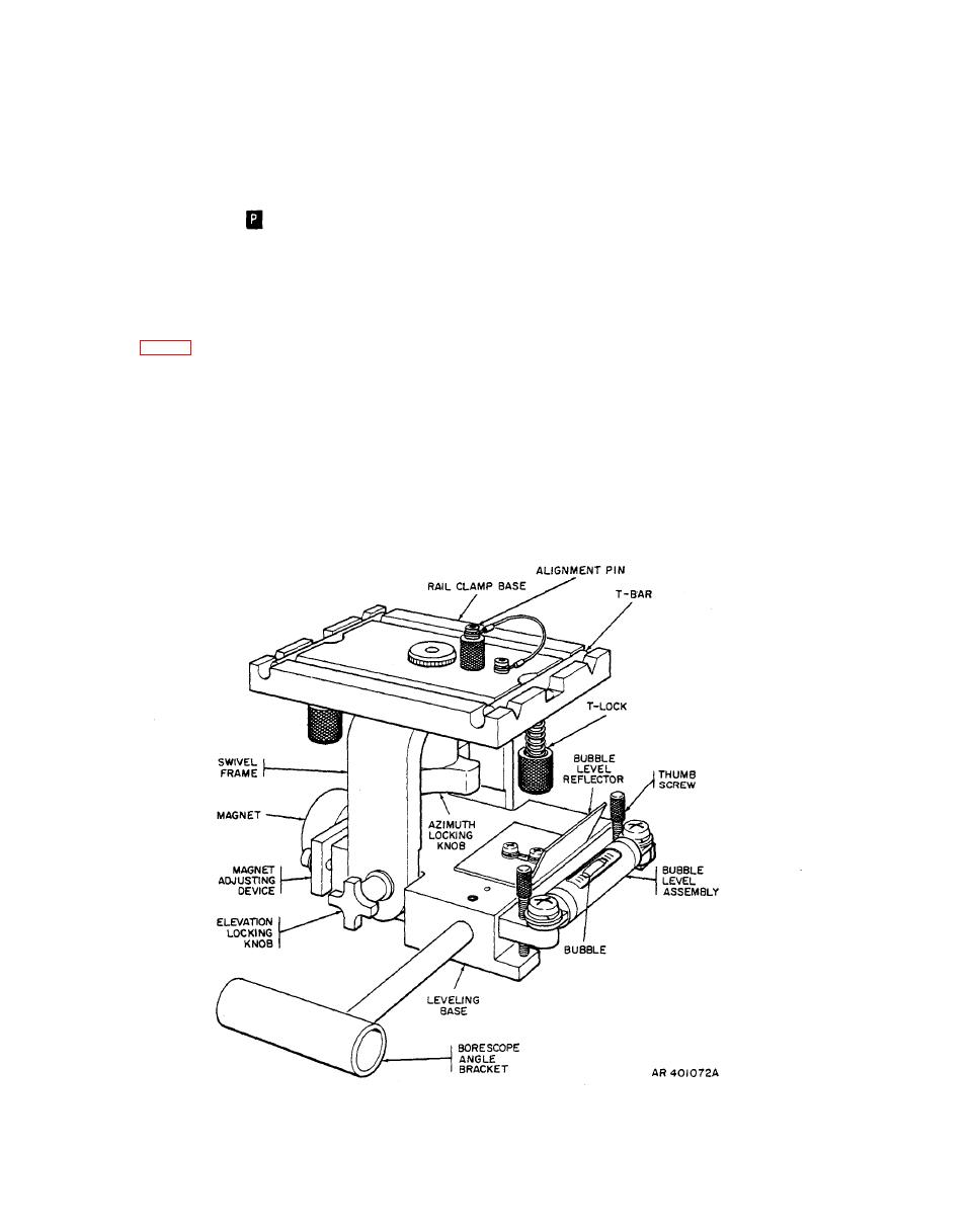
follows (fig. 4-4): Loosen the azimuth locking knob, and
rotate the rail clamp base until the 0 line on the rail clamp
(5) Insert the borescope in the LOD borescope
base is aligned with the notch in the swivel plate (mounted
bracket future and adjust the LOD in elevation until the
on top of the swivel frame). Insert the alignment pin in the
gunner's HSS target on the center target is visible. Check
hole in the rail clamp base, making sure that the alignment
that the intersection of the vertical crosshairs of the
pin is firmly seated in its hole in the swivel plate. Firmly
borescope reticle coincides with the intersection of the
tighten the azimuth locking knob.
vertical crosshairs of the gunner's HSS target.
(6) If azimuth adjustment is required, loosen the
(2) With the bubble of the LOD facing forward,
nuts on the linkage rail mounting-bracket studs (the nut
place the LOD on the TSU boresight device and center the
below each of the linkage supports).
bubble. Lock the bubble in place.
|
|
Privacy Statement - Press Release - Copyright Information. - Contact Us |