 |
|||
|
|
|||
|
Page Title:
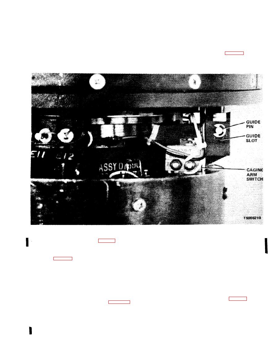
Figure 4-9. Caging arm switch adjustment. |
|
||
| ||||||||||
|
|
 TM 5-6675-250-34
(5) When the caging arm switch is actuated the
(2) Connect the GRU to the ECU and actuate
pendulum shall be automatically caged, due to
t h e caging mechanism in the BIAS mode.
r e m o v a l of power to the caging solenoid.
(3) Loosen the caging arm switch mounting
screws.
( 6 ) When correct adjustment is made, tighten
t h e switch mounting screws.
(4) The caging arm switch should be adjusted so
that it is actuated when the guide pin is in ap-
( 7 ) Install the outer shield (para 4-4d).
p r o x i m a t e l y the center of travel in the guide slot
w h e n uncaging the pendulum.
p r i m e r to the screw threads and allow to air dry.
A p p l y locking sealant, MIL-S-46163, Grade N, Type
a. Removal.
II, to the first few threads of the screws.
( 1 ) Remove the cage-uncage knob and housing
( 6 ) Position the cover and attach with screws.
c o v e r per (para 4-6).
(7) Install the setscrews partially into the knob.
(2) Unsolder and disconnect the lamp lead wires
Place the knob onto the switch shaft, allowing
f r o m terminal points E17 and E18.
sufficient space between the knob and GRU housing
(3) Remove the indicator light mounting nut
t o prevent binding. Tighten the two setscrews.
a n d remove the indicator light from the bracket.
b. Installation.
(1) Install the replacement indicator into the
a. R e m o v a l .
bracket.
( 1 ) Remove cage-uncage knob (para 4-6).
( 2 ) Prepare the mounting nut (para 2-10a).
(2) Remove the applicable cover over the
(3) Attach the indicator light to the bracket with
defective seal.
t h e mounting nut.
(3) Remove the defective seal and its adhesive.
( 4 ) Connect and solder the lamp lead wires to
CAUTION
terminals E17 and E18.
Take care not to damage the finish on the
(5) Apply MIL-S-22473, Grade N, Form R
housing.
Change 1,
|
|
Privacy Statement - Press Release - Copyright Information. - Contact Us |
