 |
|||
|
|
|||
|
Page Title:
Section II. SERVICE UPON RECEIPT OF MATERIEL |
|
||
| ||||||||||
|
|
 TM 5-6350-262-14/8
NAVELEX 0967-LP-466-9081
TO 31S9-4-31-1 Chg 1
Section II. SERVICE UPON RECEIPT OF MATERIEL
2-3. Unpacking
b. Check the equipment against the packing slip to
There are no special instructions for unpacking the
see if the shipment is complete.
Report all
balanced magnetic switch from its shipping container.
discrepancies in accordance with paragraph 1-2.
The balanced magnetic switch. Observe the usual
c. Check to see whether the equipment has been
precautions and requirements associated with handling
modified. (Equipment which has been modified will
precision electronic equipment.
have the MWO number on the top cover). Check also
to see whether all currently applicable MWO's have
2-4. Checking Unpacked Equipment
been applied.
(Current MWO's applicable to the
a. Inspect the equipment for damage incurred
equipment are listed in USASA PAM 310-6 or DA PAM
during shipment. If the equipment has been damaged,
310-7 as applicable.)
report the damage on DD Form 6 (para 1-2).
Section III. INSTALLATION INSTRUCTIONS
NOTE
The following installation procedures must be made with the assistance of direct support or
general support maintenance personnel.
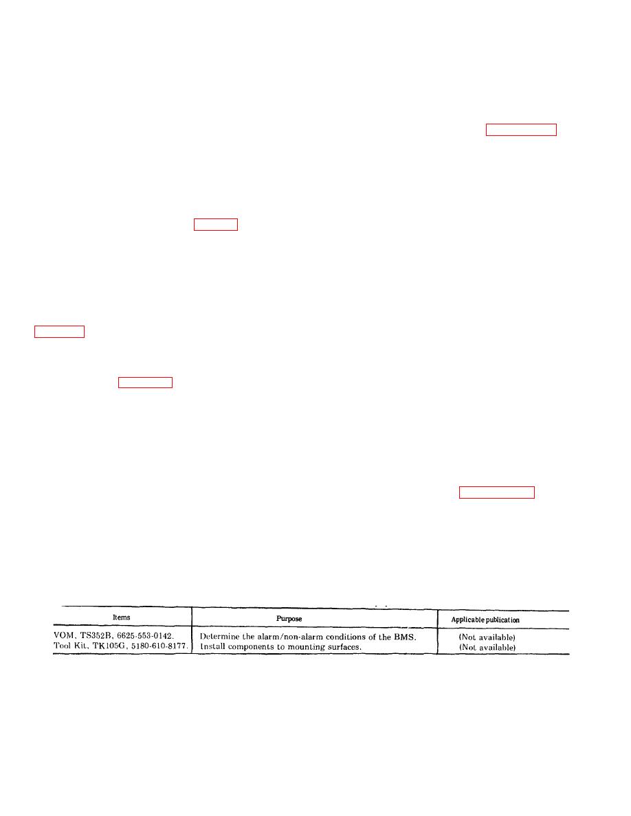
2-5. Tools, Test Equipment, and Materials Required for Installation
Table 2-1 lists all tools and equipment required to install components of the balanced magnetic switch. No special
installation tools or equipment are required.
2-6. Installation Instructions
a. General. Figure 2-1 shows the mounting dimensions of the balanced magnetic switch, and a typical mounting
configuration. The physical location of the assembly to be installed will be dictated by direct support or general support
maintenance personnel. In general the conduit should be prebent to fit the installation requirements prior to installing in
the switch assembly. The switch assembly must be installed on the conduit prior to installing the assembly on the
mounting surface. If the balanced magnetic switch is installed on a door both the door and door frame must be
constructed of steel or covered with steel plates. The switch should be mounted as near as possible to that edge of the
door opposite the hing to produce the greatest amount of travel of the actuating magnet when the door is opened.
NOTE
If the Balanced Magnetic Switch is to be mounted on a ferrous surface, the switch assembly
should be first mounted in a temporary manner and adjusted as specified in paragraph 2-8. If
the switch does not function properly, dismount the assemblies and reinstall them with standoffs
as specified in chapter 7.
b. Installation Procedure. Follow these steps to install the balances magnetic switch:
(1) Remove screws holding the cover on the switch assembly and the screws which hold together the two
halves of the magnet.
Table 2-1. Installation Tools and Test Equipment
Change 1
2-2
|
|
Privacy Statement - Press Release - Copyright Information. - Contact Us |
