 |
|||
|
|
|||
|
Page Title:
Section IV. PRELIMINARY ADJUSTMENTS |
|
||
| ||||||||||
|
|
 Section IV. PRELIMINARY ADJUSTMENTS
2-7. General
f. Open window or door, etc., a maximum of 1/2
The biasing magnet adjustment procedure contained in
inch. VOM should still indicate less than 50 ohms.
g. If VOM indicates greater than 50 ohms, repeat
installation, replacement of affected components, or at
step e, then repeat steps d through g.
any time it is believed the equipment adjustment may
have been disturbed.
h. Open window or door, etc., 1 1/4 inch. VOM
should indicate greater than 100,000 ohms.
2-8. Procedure
i. If VOM does not indicate greater than 100,000
a. Remove cover from switch assembly (refer to
ohms, loosen screw holding biasing magnet and
figure Cl).
reposition magnet until VOM indicates greater than
b. Disconnect all wires from conduit to the barrier
100,000 ohms.
Retighten screw holding biasing
strip (TB1, figure 2-2;. Label each wire for reconnection
magnet.
purposes.
j. Repeat steps d through i as often as required
c. Connect VOM between TB1-1 and-2.
until all steps are satisfactorily accomplished without
having to readjust biasing magnet.
d. Make sure door or window, etc. is closed (in
secure position). VOM should indicate less than 50
k. Disconnect VOM.
ohms.
l. Reconnect the wires removed in step b.
e. If VOM indicates greater than 50 ohms, loosen
m. Install cover.
Make sure cover is seated
two screws holding biasing magnet and reposition
properly on gasket and that the two cover screws are
magnet until VOM indicates less than 50 ohms.
tight to insure proper actuation of the tamper switch.
Retighten screws holding biasing magnet.
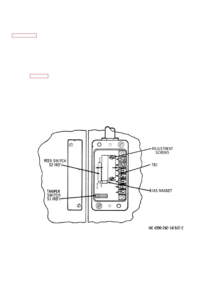
Figure 2-2. Adjustment of bias magnet.
2-3
|
|
Privacy Statement - Press Release - Copyright Information. - Contact Us |
