 |
|||
|
|
|||
|
Page Title:
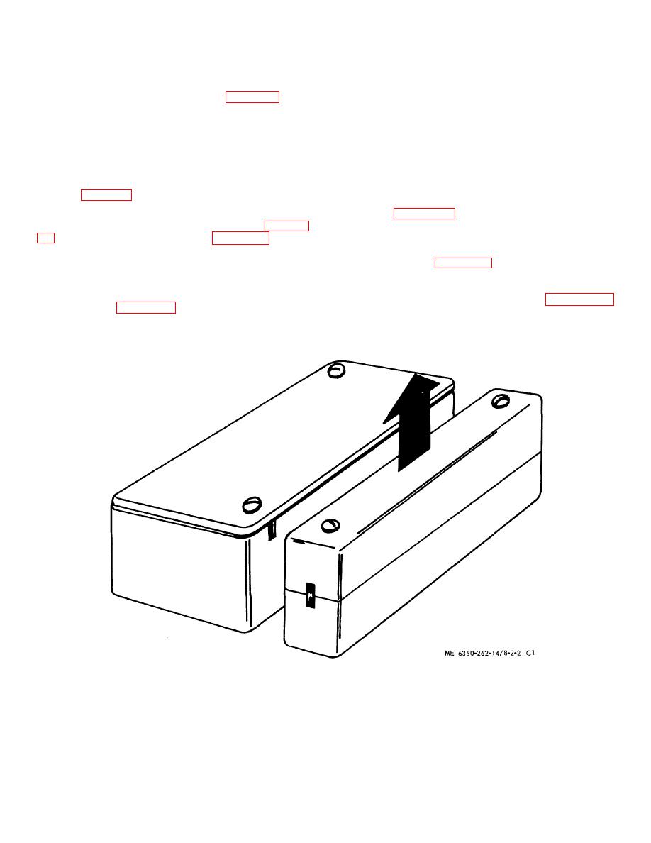
Figure 2-1A. Recommended actuation of the BMS. |
|
||
| ||||||||||
|
|
 TM 5-6350-262-14/8
NAVELEX 0967-LP-466-9081
TO 31S9-4-31-1 Chg 1
(2) Install units as shown in figure 2-1 using
should be offset 1 1/2" as shown in the figure. This
appropriate mounting hardware. The units should be
relative motion is not recommended since, to produce
positioned such that they will be in the same plane and
this motion, the Balanced Magnetic Switch is mounted
separated by a distance greater than 1/4 inch and less
outside the secure area or on a door the hinges of which
than 1 inch when the door or window is closed. The
are accessible from outside the secure area.
separation would be as narrow as possible within these
(c) If the actuating magnet is to be
limits. Note that the index marks on the magnet
installed on a door that is not constructed of steel and is
assembly and the switch assembly must be oriented as
not covered on the outside with steel plates, the door
shown in figure 2-1.
shall be covered with steel (minimum 16 gage) as
(a) Movement of the door or window
shown in figure 2-1D. The steel plating shall extend
should produce the relative motion depicted in figure 2-
from the jamb to at least one foot below the top of the
door and across the door from jamb to jamb. If the door
recommended since the switch was not designed to
frame is not constructed of steel it shall be covered with
operate in this manner.
steel as shown in figure 2-1D. The plate shall extend
across the top of the frame from jamb to jamb. The top
(b) If the switch is mounted such that
of the actuating magnet should be flush with the top
movement of the door or window produces the relative
edge of the door as shown in figure 2-1D.
motion shown in figure 2-1C, the switch assembly
Figure 2-1A. Recommended actuation of the BMS.
Change 1
2-2.1
|
|
Privacy Statement - Press Release - Copyright Information. - Contact Us |
