 |
|||
|
|
|||
|
Page Title:
Primary Batteries, Dry and Reserve Types |
|
||
| ||||||||||
|
|
 TM 5-6350-262-14/4
Even though the total energy has been reduced below operationally satisfactory limits, the battery may erupt if
shorted. Exercise caution in handling any battery. Dispose of depleted batteries in accordance with TM 11-415/TO
31-3-55, Primary Batteries, Dry and Reserve Types
a.
Batteries in the SPU will be replaced after 36 months of service. They also will be replaced anytime the
voltage level drops below 1.1 volts.
b.
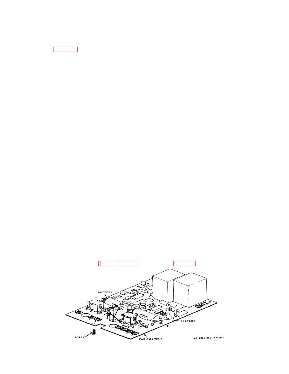
Refer to figure 6-1 and replace batteries in the SPU as follows:
(1) Set Control Unit power to SPU to OFF.
(2) Remove SPU cover.
(3) Remove PWB Assembly from SPU chassis; retain screws.
Warning
Applying heat to a mercury battery will accelerate chemical reactions within the cell(s) Excessive
heat could result in an explosion. Use heat sink between battery and soldering iron when
unsoldering battery leads. Soldering iron rating should not exceed 40W.
(4) Unsolder battery leads from terminals:
(a)
Attach heat sinks to outer battery leads.
(b) Unsolder outer battery leads (pull leads free with pliersr
(c)
Wipe excess solder from terminals.
(d)
Transfer heat sinks to inner battery leads.
(e)
Unsolder inner battery leads (pull leads free with pliers).
(f)
Wipe excess solder from terminal.
(g)
Remove heat sinks.
(5) Remove batteries from clips.
(6) Check voltage of replacement batteries (para
Note
The case of the battery is positive (+); the center electrode with the insulating washer is negative
(-L
(7) Orient each battery so that polarity matches mark on board.
(8) Attach battery leads to terminals.
Warning
Applying heat to a mercury battery will accelerate chemical reactions within the cell(s).
Excessive heat could result in an explosion. Use heat sink between battery and soldering iron
when soldering battery leads Soldering iron rating should not exceed 40W.
(9) Solder battery leads to terminals:
(a)
Attach heat sinks to outer terminals.
(b)
Solder outer leads to respective terminals
(c)
Transfer heat sinks to inner leads
(d)
Solder inner leads to shared terminal.
(e)
Remove heat sinks.
(10) Reinstall PWB Assembly on SPU chassis
(11) Set Control Unit power to SPU to ON.
(12) Perform functional check (para 2-9 and 2-10) or bench check (para 6-19) to verify repair.
Figure 6-1. Battery Replacement
6-3
|
|
Privacy Statement - Press Release - Copyright Information. - Contact Us |