 |
|||
|
|
|||
|
Page Title:
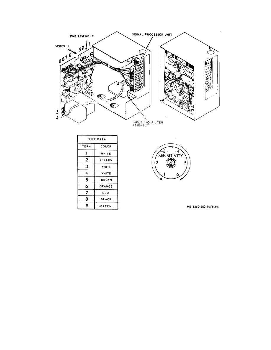
Figure 2-4. Installing PWB Assembly |
|
||
| ||||||||||
|
|
 TM 5-6350-262-14/4
Figure 2-4. Installing PWB Assembly
2-9. Functional Checkout of MWS
Note. The following procedure is concerned only with the functional checkout of the MWS If used as part of a J-
SIIDS system functional checkout, two-way communication must be provided between the JSIIDS Monitor Unit operator
and the MWS installation crew. Monitor Unit and Control Unit control settings will be in accordance with the technical
manuals for those equipment
a. External power (20 1 vdc) must be supplied to the SPU to energize the alarm output relays (through the tamper
switch contacts. This power is supplied by the J-SIIDS Control Unit. (Both i115 vac and 20 vdc power switches inside
the control panel must be ONM
b. For functional checkout of the MWS, the control switch on the front panel of the Control Unit will be set to
TEST/RESET. Thus set, the Control Unit will emit a 10-second audible alarm, when triggered by the SPU. The Control
Unit will then reset automatically.
c. Perform the functional checkout of the MWS as follows: (1) Open control panel and set Control Unit power
switches to ON.
(2) Close control panel and set Control Unit control switch to TEST/RESET. (Allow 5 minuets for circuits to
stabilize)
2-7
|
|
Privacy Statement - Press Release - Copyright Information. - Contact Us |
