 |
|||
|
|
|||
|
Page Title:
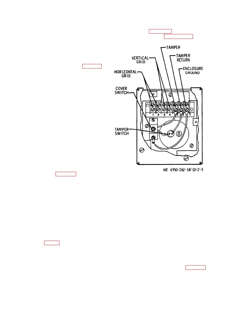
Figure 2-3. Terminal strip connections. |
|
||
| ||||||||||
|
|
 terminal lug and crimp with the crimpers supplied
center screw. Then pull the wire back through the
with the kit.
body of gun.
(17) Attach each terminal lug to the terminal
NOTE
Adjust the tension and adjust knob and practice
strip as shown in figure 2-3, and perform the
stapling on a piece of material on which grid wire is to be
installation checkout test of paragraph 2-7.
installed, until correct tension is obtained for staples to
securely attach grid wire. Lock the adjust knob in place
by tightening the knurled knob against the body of the
installation gun.
(4) Start stapling wire to the panel, four inches
up from the bottom and four inches in from the side
of the lower right corner of the panel. See figure 2-1.
(5) Proceed vertically up the wall panel placing
staples 12 inches apart.
(6) When within four inches from top of the
panel, move four inches horizontally to the left and
proceed vertically down the wall, placing staples 12
inches apart. When within four inches from bottom
of panel, move four inches horizontally to the left
again and proceed vertically up the panel. Repeat
this step until the last vertical wire is approximately
four inches from the left side of the panel.
(7) Run the wire back to where the wire
originated. Cut the wire, leaving approximately one
foot of free wire past the final staple.
(8) If it becomes necessary to reload installation
gun while applying wire to the panel, open the spare
staple magazine, rotate gun until magazine is
pointing slightly down and remove one strip of
staples. Load the gun and then continue stapling.
(9) After applying the vertical wire grid, start
again in the lower right hand corner of the panel and
repeat steps (3) through (7) except proceed horizon-
tally across the panel. See figure 2-1.
(10) After the grid wire (horizontal and vertical)
has been applied to the panel, cover the panel with
Figure 2-3. Terminal strip connections.
another piece of paneling.
(11) Take a small piece of sand paper and fold in
(18) Replace junction box cover after J-SIID
half so that the rough sides of the sandpaper are
system wiring has been completed.
facing each other.
c. Window, Skylight Installation Prodecure.
(12) By placing the wire between the folded
Perform the following steps to install the grid wire
paper and pulling the wire, remove the insulation
sensor:
from the last two or three inches of the wire. Repeat
(1) Locally obtain length of 1/2 inch diameter
for all four wires
wooden dowel rod. Put a slot (1/16 in. wide x 1/16 in.
(13) Remove the top cover from the junction box.
deep) parallel to axis of the dowel.
Insert wires through hole in back of the box.
(2) Nail slotted doweling to window or skylight
(14) Mount junction box to the panel, using the
frame. These dowels should be spaced four inches
four mounting holes (fig. 2-2) in the back of the box.
apart running vertically over the area to be covered.
(15) Take one of the wires and fold it in the middle
The slot should be facing the inside of the room.
of the section where the insulation was removed.
(3) Run the Did wire vertically up and down the
Fold it again in the middle of the first fold. Repeat
window in the dowel slots. The wire should be stapled
this for all four wires.
in the slot every 12 inches as shown in figure 2-4.
(16) Insert folded section of each wire into
2-4
|
|
Privacy Statement - Press Release - Copyright Information. - Contact Us |