 |
|||
|
|
|||
|
Page Title:
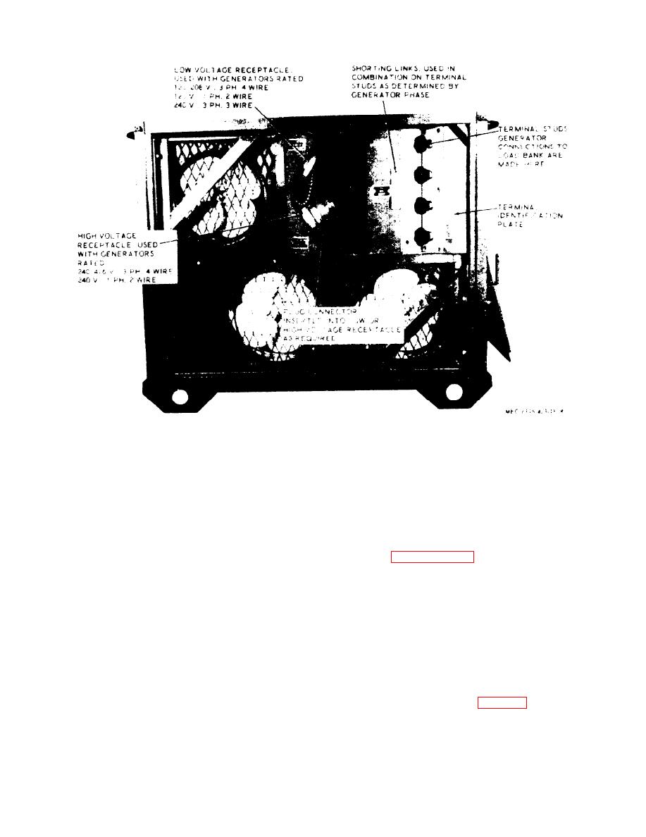
Figure 8. Controls and instruments-baffle assembly |
|
||
| ||||||||||
|
|
 TM 5-6115-423-15
Figure 8. Controls and instruments-baffle assembly.
d. Remove mounting bolts or tie down rods,
be blocked at the base and sides to prevent
cables or lashing that fasten load bank to its
shifting during transit. The load bank is de-
foundation, skid or trailer.
signed to withstand an acceleration of 2.5 g
for a period of 0.10 seconds applied along
e. Enclose the tester in an envelope of water
each of the three major axis in both directions.
resistant barrier material and seal with water-
proof pressure sensitive tape.
12. Reinstallation After Movement
f. Encase the load bank and its envelope of
water resistant barrier material in a strong
Refer to paragraph 10 (Installation or
wooden crate or box of adequate size. When
Setting-Up Instructions) for procedure in re-
shipped by truck, rail, or air the unit should
installing the load bank after movement.
Section Ill. CONTROLS AND INSTRUMENTS
ments for proper operation of the load bank.
13. General
14. Controls and Instruments
This section describes, locates, illustrates and
furnishes the operator, crew or organizational
The purpose of the controls and instruments
maintenance personnel with sufficient infor-
and the normal and maximum reading of the
mation about the various controls and instru-
instruments are illustrated in figure 7.
13
|
|
Privacy Statement - Press Release - Copyright Information. - Contact Us |
