 |
|||
|
|
|||
|
Page Title:
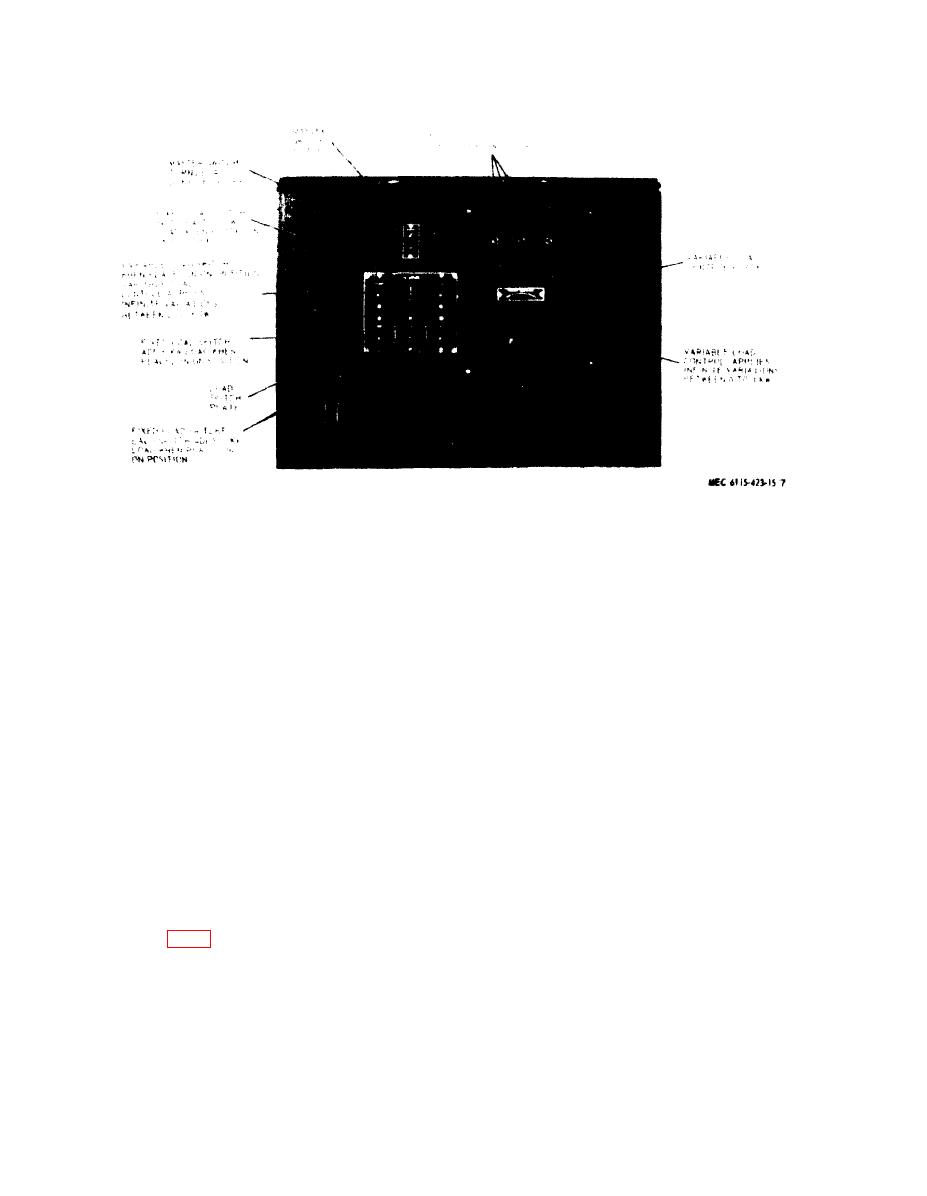
Figure 7. Controls and instruments-control panel |
|
||
| ||||||||||
|
|
 TM 5-6115-423-15
Figure 7. Controls and instruments-control panel.
ation either on its own base or secured to
When exposed to high mositure conditions
pallet, trailer, or skid. It is advisable to set
particularity in warm climates, components
up and use the load bank in an area with
such as fan motors, selenium rectifiers, and
sufficient ventilation and free from corrosive
variable transformer should be treated to make
atmospheres or oily contaminants. Keep clear
them moisture and fungus resistant. Housing
of hazardous electrical connections or wires.
can be sprayed with a varnish which offers
Assure adequate working space for con-
protection against these hazards.
venience and safety. Store in dry, clean area
C . Indoor In.stallation. The load bank
and cover to keep dust off the load bank.
should be set up in level position for best oper-
Section Il. MOVEMENT TO NEW WORKSITE
(4) Disconnect leads to tested equipment
11. Dismantling for Movement
terminal strip. Secure copper short-
Disconnect the load bank from power plant
ing links to cabinet by threaded stud
before removing parts or assemblies. Procedure
and wing nut. Electrical leads and cir-
for dismantling the load bank in preparation
cuits should not be removed unless
for moving to a new worksite is to:
their purpose is understood. Tag all
leads and terminals to identify them
a. Disconnect the load as follows:
for reinstallation.
(1) Rotate the variable load control knob
b. Inspection interior components for securi-
(fig. 7) full counterclockwise.
ty in mounting.
(2) Place all fixed load switches 3
c. Close and lock air exhaust door, control
through 7 in OFF position.
panel door and other panels. Cover seams with
(3) Stop tested equipment.
pressure sensitive waterproof tape.
12
|
|
Privacy Statement - Press Release - Copyright Information. - Contact Us |