 |
|||
|
|
|||
|
Page Title:
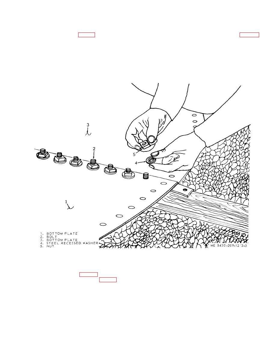
Figure 3-3. Bottom plates installed. |
|
||
| ||||||||||
|
|
 TM 5-5430-209-12
3-3. Installation of Tank Bottom
o. With the plate resting on boards, remove nuts
from all bolts. Apply gasket (4, fig. 3-2) to the bolts with
smooth-mouth tool. Cut gasket the full length of the lap
over the bolts (2), in the lap seam of plate (3). Apply
seam plus an overlap of l'2 -bolt holes at each end. As
washer (4) to the bolts (2). Make sure that cup side of
the gasket is applied, check to see that the bolt head
washers is facing down.
sets square in the channel. Remove bolt backing
boards
Figure 3-3. Bottom plates installed.
CAUTION
at center of tank bottom. Apply nuts (5, fig. 3-3) to all
Tighten bolts a maximum of 40 to 50
bolts (2) in the lap seam of the plates. Make sure that
footpounds of torque. Over-tightening
rounded face of nut is bearing against washer; tighten all
will damage the strip gasket.
bolts.
3-4
|
|
Privacy Statement - Press Release - Copyright Information. - Contact Us |
