 |
|||
|
|
|||
|
|
|||
| ||||||||||
|
|
 TM 5-5430-209-12
3-2. Assembly of Tank Bottom
f. Work from the ground face of right bottom plate
(4) and push bolts (7) through bolt holes of flanged
opening. Place blocking under bolt and flange assembly
2-inch pipe plug (1) made up in the 2-inch pipe coupling
to hold it in position.
(2). No additional assembly work is required.
g. Slip gasket (6) over bolts (7) and force it down
b. The right bottom plate (4) is fitted with a 2 inch
against the inside face of plate (4).
pipe plug (1) made up in the 2-inch pipe coupling (2). A
h. Slip outside flange half (10) over bolts (7) with
6-inch blind flange set is assembled on the plate to
machined face of flange facing the gasket.
complete the assembly.
i. Apply nuts (5) to bolts (7). Tighten the bolts.
c. Block up plate (4) 6 inches off the ground. Cut
Remove plate from blocking and lay it on tank
six 1-hole gaskets (9) from gasket material. Force a
foundation.
gasket over and against the head of each bolt (7).
j. Use short pieces of 2 by 4's as blocking, and
d. Insert bolts through bolt holes in flange half (10)
raise the lap seam end of right bottom plate (4). This
from outside face of flange with heads of bolts fitting
will simplify the work of attaching channel (2, fig. 3-2) to
into the cutouts provided.
e. Place bolt-retaining boards on the ground.
the right bottom plate (4, fig. 3-1). Set blocking in
about 6 inches from edge of plate to clear the channel.
Position flange assembly with bolt head resting on
boards. Slip gasket (6) over bolts and force it down
against the inside face of flange (8) using a round,
smooth-mouth tool.
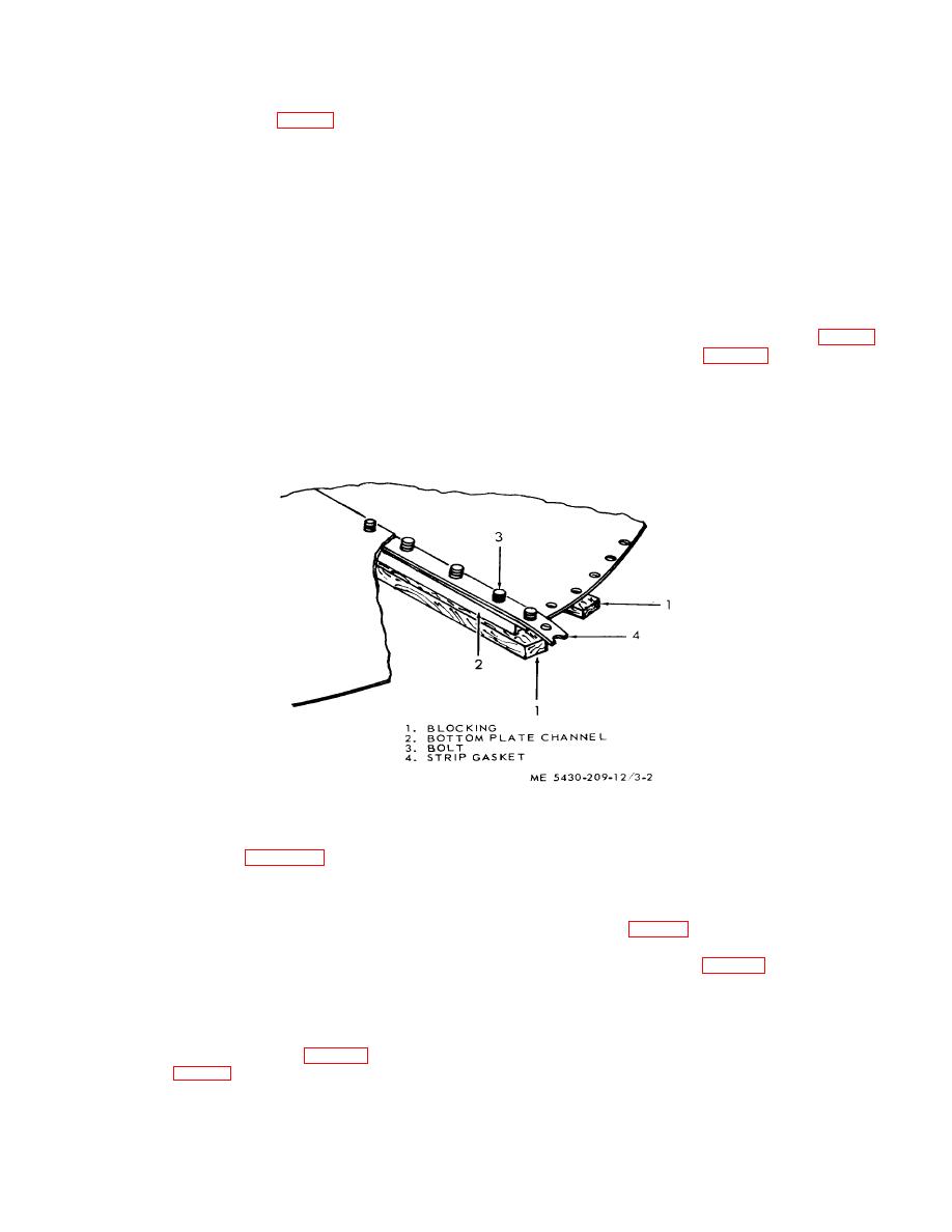
Figure 3-2. Channels, bolts, and gaskets installed on bottom plate.
finger-tighten to hold channel in a temporary position
while completing installation of the remaining bolts.
lap seam of the plates at center of tank bottom during
m. Count off 5-bolt holes on each side of the center
final installation, 11 each 1/2-by 11/2-inch bolts are
required in the lap seam to attach the ladder brace to
bolt and install 10 each i/2 -by 1 ''2 inch bolts. Insert by
the tank bottom.
1'4 inch bolts (3, fig.
NOTE
Apply a nut to each bolt and finger-tighten.
To Insure that the ladder brace bolts are
properly installed mark center bolt hole
plate and lay bolt backing boards under bolt heads as a
in bottom plate and bottom plate
blocking is removed.
channel
l. Insert a ' ,-by '2 -inch bolt through center bolt
hole of bottom plate channel (2, fig. 3-2) and right
bottom plate (4, fig 3-1). Apply a nut to the bolt and
3-3
|
|
Privacy Statement - Press Release - Copyright Information. - Contact Us |
