 |
|||
|
|
|||
|
Page Title:
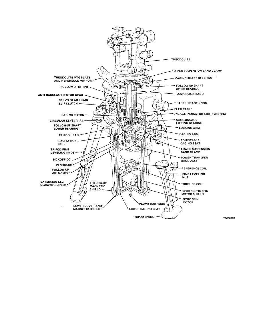
Figure 1-5. Gyroscopic reference unit - cutaway |
|
||
| ||||||||||
|
|
 TM 5-6675-250-34
condition of the follow-up shaft, the worm gear is
(1) The housing contains the follow-up shaft,
mounted with a preloaded pair of ball bearings. The
the servo gear train and the pendulum mechanism.
two speed gear head is provided to give the follow-up
The follow-up shaft is mounted to the housing
shaft ample angular velocity to track the pendulum
through a pair of preloaded ball bearings. The shaft
from 40 off of the meridian, yet have enough
engages a single lead worm at the gear train output
resolution to position the shaft as the pendulum is
through an anti-backlash worm wheel. This
damped to the meridian. Force for caging t h e
arrangement provides a locked condition of the GRU
pendulum is obtained through a lever which has one
output when the servo motor is de-energized after
end attached to the housing. The upper pendulum
gyrocompass is complete. The servo gear train is
caging seat is attached to the center of the lever and
mounted to the housing structure. It consists of a
the movable end of the lever is connected to a crank.
servo motor which drives a two speed gear head
The crank is mounted on a shaft which is rotated
which in turn drives the output worm through
through a worm gear. The gear is then driven by the
several spur gears. To assure the needed locked-up
|
|
Privacy Statement - Press Release - Copyright Information. - Contact Us |
