 |
|||
|
|
|||
|
|
|||
| ||||||||||
|
|
 TM 9-2350-238-20-1
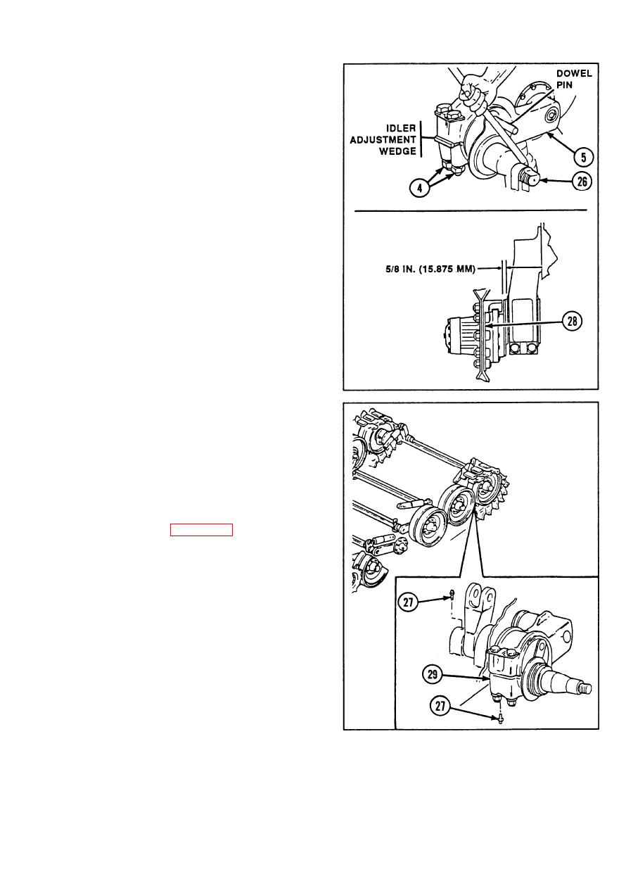
Loosen two self-locking nuts (4).
34
Drive in idler adjustment wedge far
35
enough so threads on idler wheel spindle
(26) engage threads on pivot arm
assembly (5).
Temporarily install suitable dowel pin.
36
Protect idler wheel spindle (26) bearing
37
surface by wrapping with clean wiping
rags.
38
Insert bar between dowel pin and idler
wheel spindle (26).
39
Screw idler wheel spindle (26) into pivot
arm assembly (5) until the outer face of
idler wheel spindle is 5/8 in. (15.9 mm)
from outer face of pivot arm assembly.
Dowel and idler wheel arm spindle should
align 90 degrees from the pivot arm
assembly center line.
40
Remove idler adjustment wedge and
dowel pin.
41
If removed, install lubrication fittings (27).
Install idler wheel vehicular wheel hub
42
(28). Refer to page 2-884.
Lubricate pivot arm assembly (5) and idler
43
wheel arm and hub assembly (29). Refer
to TM 9-2350-238-10.
Tighten two self-locking nuts (4). Torque
44
to 575 to 600 ft-lb (780 to 848 N-m).
2-863
|
|
Privacy Statement - Press Release - Copyright Information. - Contact Us |
