 |
|||
|
|
|||
|
|
|||
| ||||||||||
|
|
 TM 8-2350-238-20-1
2-155. MAINTENANCE OF LOCKOUT CYLINDER AND RELATED PARTS (CONT).
NOTE
The following procedures are written for one lockout cylinder, but apply to all
q
lockout cylinders.
For right side number 1 and number 2 lockout cylinders, gain access through
q
right side of powerplant compartment.
For right side number 3 and number 4 lockout cylinders, gain access through
q
bottom right front of turret well.
For left side number 1 and number 2 lockout cylinders, gain access through
q
bottom rear of drivets compartment.
For left side number 3 lockout cylinder, gain access through bottom left front of
q
turret well.
For left side number 4 lockout cylinder, gain access through bottom left rear of
q
turret well.
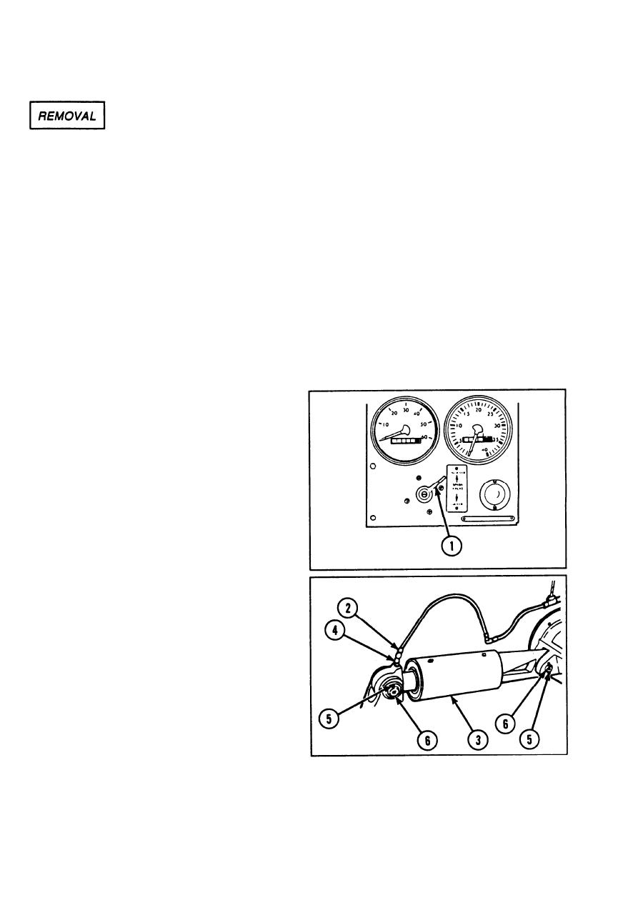
1 Set SPNSN VALVE handle (1) to UN-
LOCKED.
2
Disconnect hydraulic hose connector (2)
from lockout cylinder (3).
3
Cover fitting connector (4).
4
Cap hydraulic hose connector (2) with
masking tape in upright position against
hull to prevent oil drainage.
Remove two cotter pins (5) from each
5
headless straight pin (6).
2-884
|
|
Privacy Statement - Press Release - Copyright Information. - Contact Us |