 |
|||
|
|
|||
|
|
|||
| ||||||||||
|
|
 TM 9-2350-238-20-1
2-148. MAINTENANCE OF IDLER WHEEL ARM AND HUB ASSEMBLY AND
ATTACHING PARTS, AND IDLER WHEEL ARM AND HUB (CONT).
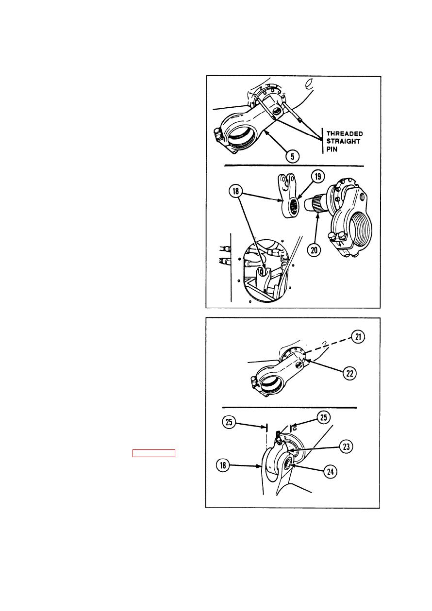
REASSEMBLY/lNSTALLATION (CONT)
Install two threaded straight pins into
23
opposing capscrew holes of pivot arm
assembly (5).
24
Coat sealing surfaces of pivot arm
assembly (5) with sealing compound.
25
Position pivot arm assembly (5) on
threaded straight pins.
Push pivot arm assembly (5) into housing
26
until end of arm is visible in arm cavity of
roadwheel lever (18).
27
Insert and position roadwheel lever (18)
into lockout cylinder lever arm cavity.
28
Position roadwheel lever (18) so blind
spline (19) on lever arm mates with blind
spline (20) on pivot arm assembly.
29
Remove two threaded straight pins.
Install and tighten nine new Iockwashers
30
(21) and nine hexagon head capscrews
(22) in cross-pattern sequence,
Install lockout cylinder eye (23) in road-
31
wheel lever (18).
Install straight headless pin (24) and two
32
new cotter pins (25).
33
Install torsion bar. Refer to page 2-827.
2-862
|
|
Privacy Statement - Press Release - Copyright Information. - Contact Us |
