 |
|||
|
|
|||
|
Page Title:
GENERATOR OUTPUT CIRCUIT. (Cont) |
|
||
| ||||||||||
|
|
 TM 9-2350-238-20-1
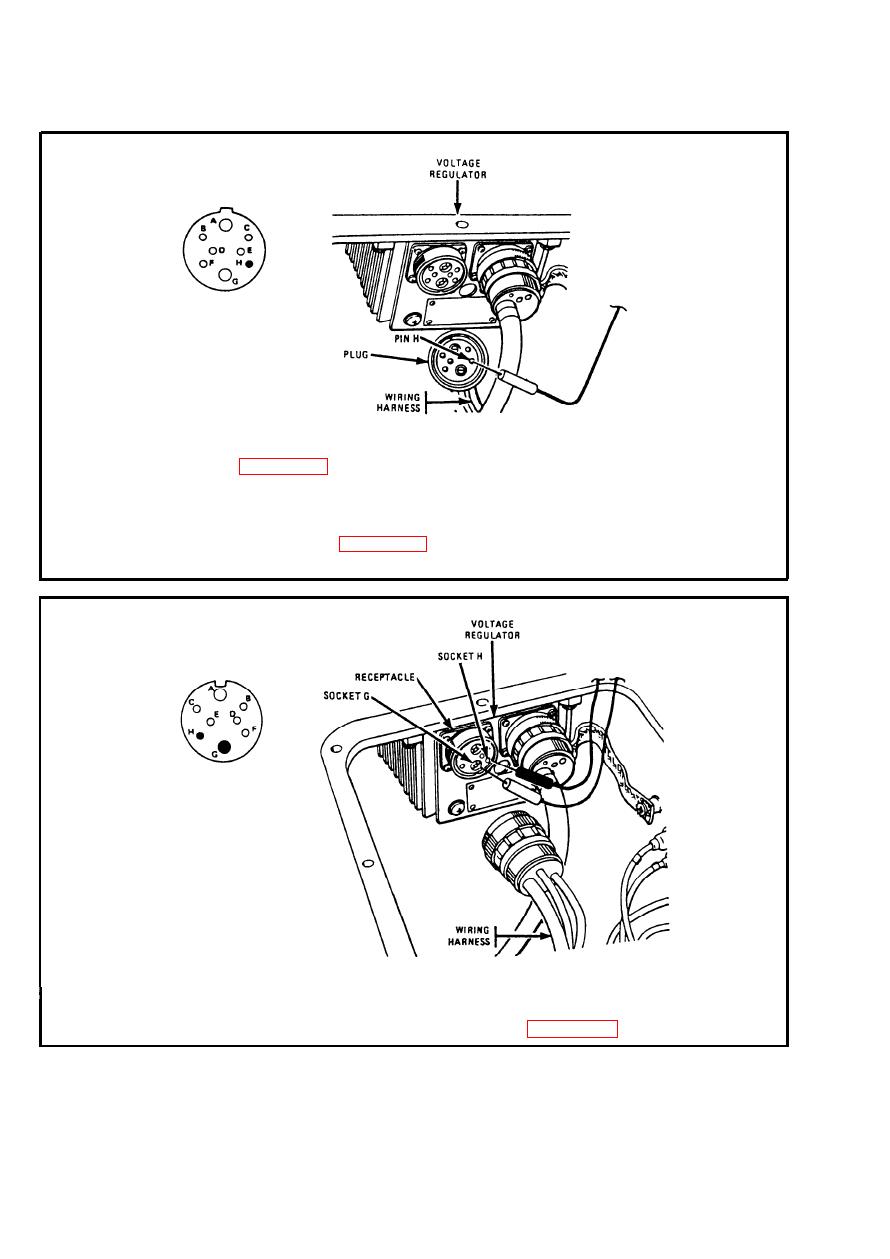
2-12. ELECTRICAL CIRCUIT TROUBLESHOOTING (CONT).
Step 2.
To access voltage regulator, remove left CO2 cylinder access cover. Refer
to page 2-923. Disconnect wiring harness from voltage regulator. Place
red probe on plug pin H (lead 506). Ground black probe. Set MASTER
and INST switches ON. If multimeter indicates about 24 volts, go to step
3. If multimeter indicates no voltage, troubleshoot generator warning light
circuit. Refer to page 2-177. Connect wiring harness to voltage regulator.
Set MASTER and INST switches OFF.
Step 3.
Check continuity between receptacle sockets G (lead 2) and H (lead 506)
on voltage regulator. If continuity exists, go to step 4. If no continuity
exists, replace voltage regulator. Refer to page 2-557.
2-134
|
|
Privacy Statement - Press Release - Copyright Information. - Contact Us |
