 |
|||
|
|
|||
|
|
|||
| ||||||||||
|
|
 TM 9-2330-202-14&P
4-50.
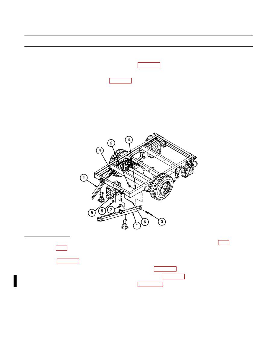
DRAWBAR REPLACEMENT (CONTINUED).
5.
Pull drawbar (1) forward, away from vehicle, and remove.
6.
If replacing drawbar (1), remove data plate (para 4-63).
b.
INSTALLATION
1.
If removed, install data plate (para 4-63).
2.
Position drawbar (1) under frame and support with jackstand.
3.
Loosely install drawbar (1) on two eyebolts (8) with spacer (7), capscrew (6), and new self-locking nut
(5). Torque self-locking nut (5) between 35 and 40 Ib-ft (47-54 Nm).
4.
Loosely install drawbar (1) on front spring hanger (4) with capscrew (3) and new self-locking nut (2).
Torque self-locking nut (2) between 140 and 150 Ib-ft (190-203 Nm).
5.
Remove supports from rear of vehicle.
438-104
FOLLOW-ON TASKS:
Install hydraulic brake lines on curb-side drawbar, if installing curb-side drawbar (para
Install chassis wiring harness on road-side drawbar, if installing road-side drawbar
Install intervehicular cable on road-side drawbar (para 4-30).
Install hydraulic brake actuator assembly if removed (para 4-38).
Install fixed front support leg if removed (para 4-51.1).
4-100
Change 2
|
|
Privacy Statement - Press Release - Copyright Information. - Contact Us |
