 |
|||
|
|
|||
|
|
|||
| ||||||||||
|
|
 TM 9-2320-360-20-2
11-4.2. SLACK ADJUSTER (AUTOMATIC - AXLES NO. 2, 3 & 4) REPL (CONT)
c. Installation
NOTE
Install slack adjuster so that pawl
faces away from brake drum.
Axles no. 2 and no. 3 do not
have a snap ring between axle
housing and washer.
Washers should be installed as
marked during removal.
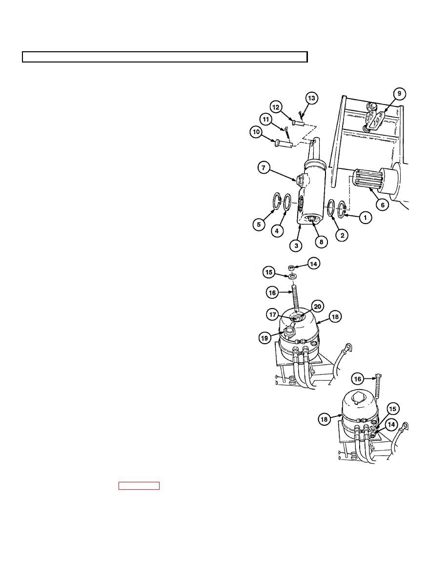
(1) Install snap ring (1), washer(s) (2), slack
adjuster (3), washer(s) (4), and snap ring
(5) on brake camshaft (6).
CAUTION
The pawl must be pulled out when
rotating the manual adjusting nut.
Failure to comply will result in
damage to slack adjuster.
(2) Pull pawl (7) out while turning adjusting
screw (8) clockwise until holes in clevis (9)
and slack adjuster (3) are aligned.
(3) Install pin (10) through clevis (9) and slack
adjuster (3).
(4) Install new cotter pi n (11) in pin (10).
(5) Install pin (12) through clevis (9) and slack
adjuster (3).
(6) Install new cotter pin (13) in pin (12).
(7) Loosen and remove nut (14) and washer
(15) from tool (16).
(8) Push
tool
(16)
down,
turn
counterclockwise 90. Pull out of slot (17)
inside brake chamber (18).
(9) Install dust cap (19) in access hole (20).
(10) Install tool (16), washer (15), and nut (14)
in mounting position on brake chamber
(18). Tighten nut.
d. Follow-On Maintenance
(1) Grease slack adjuster (LO 9-2320-360-
12).
(2) Adjust brakes (para 11-2.1).
Change 3 11-11
|
|
Privacy Statement - Press Release - Copyright Information. - Contact Us |