 |
|||
|
|
|||
|
|
|||
| ||||||||||
|
|
 TM 9-2320-360-20-2
CAUTION
The pawl must be pulled out when
rotating the manual adjusting nut.
Failure to comply will result in
damage to slack adjuster.
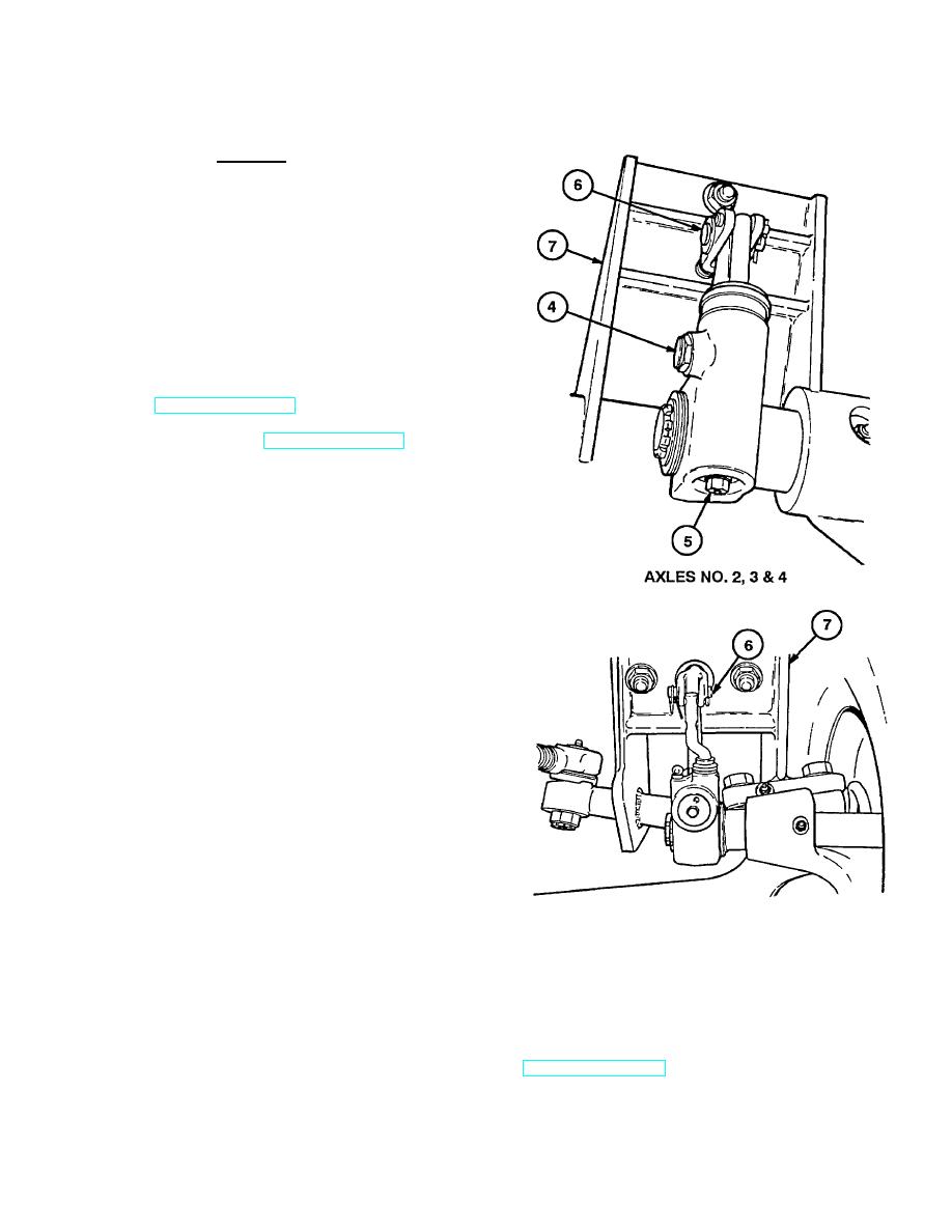
(4) Pull pawl (4) out while turning adjusting
screw (5) clockwise until tight.
(5) Pull pawl (4) out while turning adjusting
screw (5) counterclockwise 1/2 turn.
(6) Start engine an d build system air pressure
to
120-125
psi
(827-862
kPa)
(TM 9-2320-360-10).
(7) Shut off engine (TM 9-2320-360-10).
(8) Measure distance between center of large
clevis pin (6) and brake chamber bracket
(7) with brake treadle released. Record
measurement.
(9) Measure distance between center of large
clevis pin (6) and brake chamber bracket
(7) while assistant holds brake treadle
down. Record measurement.
NOTE
If air chamber stroke is not within
specifications, turn adjusting screw
clockwise 1/8 turn and repeat steps
(8) thru (10).
(10) The difference between measurements
made in step (8) and (9) is the air
chamber stoke. Air chamber stroke must
be 2 in. (50 mm), or less when properly
adjusted.
(11) Pull out PARKING BRAKE control (1) to
apply brakes.
AXLE NO. 1
b. Follow-On Maintenance
(1) Remove wheel chocks.
(2) Drive HET Tractor and check service brake operation (TM 9-2320-360-10).
Change 3 11-3
|
|
Privacy Statement - Press Release - Copyright Information. - Contact Us |