 |
|||
|
|
|||
|
|
|||
| ||||||||||
|
|
 TM 9-2320-360-20-2
c. Assembly
NOTE
Do step (1) only if electrical
contact(s) are being replaced.
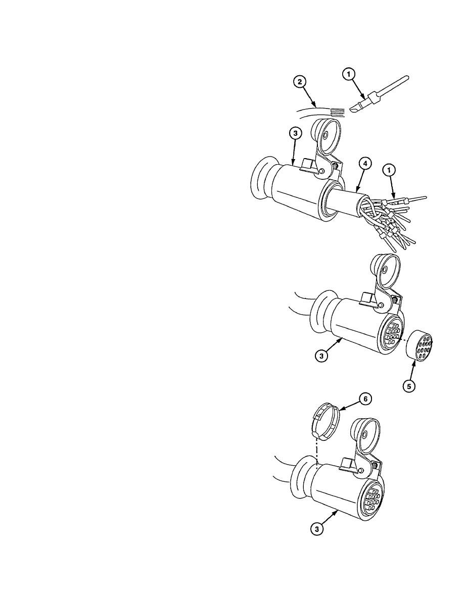
(1) Solder new electrical contact (1) on wire
(2).
NOTE
Silicone spray can be applied to
cable for easier assembly into shell.
(2) Install shell (3) on cable (4).
CAUTION
A multimeter must be used to verify
the proper positioning of the
electrical contacts in the insert.
Failure to comply may result in
improper assembly and damage to
equipment
(3) Place lead of multimeter on one electrical
contact (1).
(4) Find the corresponding electrical contact
on the other end of the cable using the
multimeter.
(5) Insert the correct electrical contact in
position "A" of both inserts (5).
(6) Repeat steps (3) thru (5) for remaining 11
shell positions "B" thru "N".
CAUTION
Insert must be properly positioned in
shell for proper light operation.
Notch in end of shell must be located
between pins/sockets "A" and "J".
Failure to comply may result in
damage to equipment.
(7) Install insert (5) in shell (3).
(8) Install clamp (6) on shell (3).
7-290 Change 1
|
|
Privacy Statement - Press Release - Copyright Information. - Contact Us |