 |
|||
|
|
|||
|
|
|||
| ||||||||||
|
|
 TM 9-2320-360-20-2
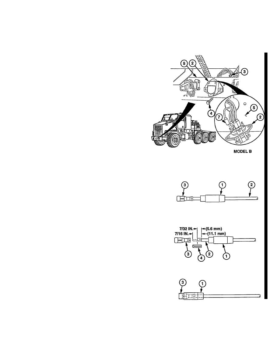
(5) Remove two locknuts (3) and screws (4)
from electrical connector (2).
Discard
locknuts.
NOTE
Wires are removed by pulling seal
boots
out
of
electrical
connectors.
Tag and mark all wires before
removal.
(6) Remove
wires
(7)
from
electrical
connector (2).
b. Installation
NOTE
Do steps (1) thru (11) for Model B
connector.
Do steps (12) thru (18) for Model
A connector.
Do steps (4) thru (11) if replacing
model A connector with Model B
connector.
Do steps (1) thru (8) if terminal or
seal boot is damaged on Model B
connector.
Tapered end of seal boot is
installed on wire first.
(1) Slide seal boot (1) over wire (2) to expose
terminal (3).
(2) Cut off terminal (3) at end of wire (2).
NOTE
Do steps (3) and (4) if seal boot is
damaged.
(3) Remove seal boot (1) fr om wire (2) and
discard.
(4) Install new seal boot (1) on wire (2).
(5) Remove 7/16 in. (11.1 mm) of insulation
(4) from end of wire (2).
(6) Fold over bare end of wire (2) to 7/32 in.
(5.6 mm).
(7) Install new terminal (3) on wire (2).
(8) Slide seal boot (1) over terminal (3).
(9) Apply corrosion preventative compound to
front of terminals (3) and seal boots (1).
Change 2 7-181
|
|
Privacy Statement - Press Release - Copyright Information. - Contact Us |