 |
|||
|
|
|||
|
Page Title:
7-PIN ELECTRICAL CONNECTOR REPLACEMENT |
|
||
| ||||||||||
|
|
 TM 9-2320-360-20-2
7-60. 7-PIN ELECTRICAL CONNECTOR REPLACEMENT
This task covers:
a. Removal
c. Follow-On Maintenance
b. Installation
INITIAL SETUP
Equipment Conditions
Materials/Parts
Batteries disconnected (para 7-61).
Adhesive-Sealant, Silicone (Item 3, Appendix C)
Compound, Corrosion Preventati ve (Item 14.1,
Tools and Special Tools
Tool Kit, Genl Mech (Item 54, Appendix F)
Tags, Identification (Item 32, Appendix C)
Tool Kit, Electrical Repair (Item 53, Appendix F)
Locknuts (4) (Item 72, Appendix G)
Locknuts (2) (Item 68, Appendix G)
NOTE
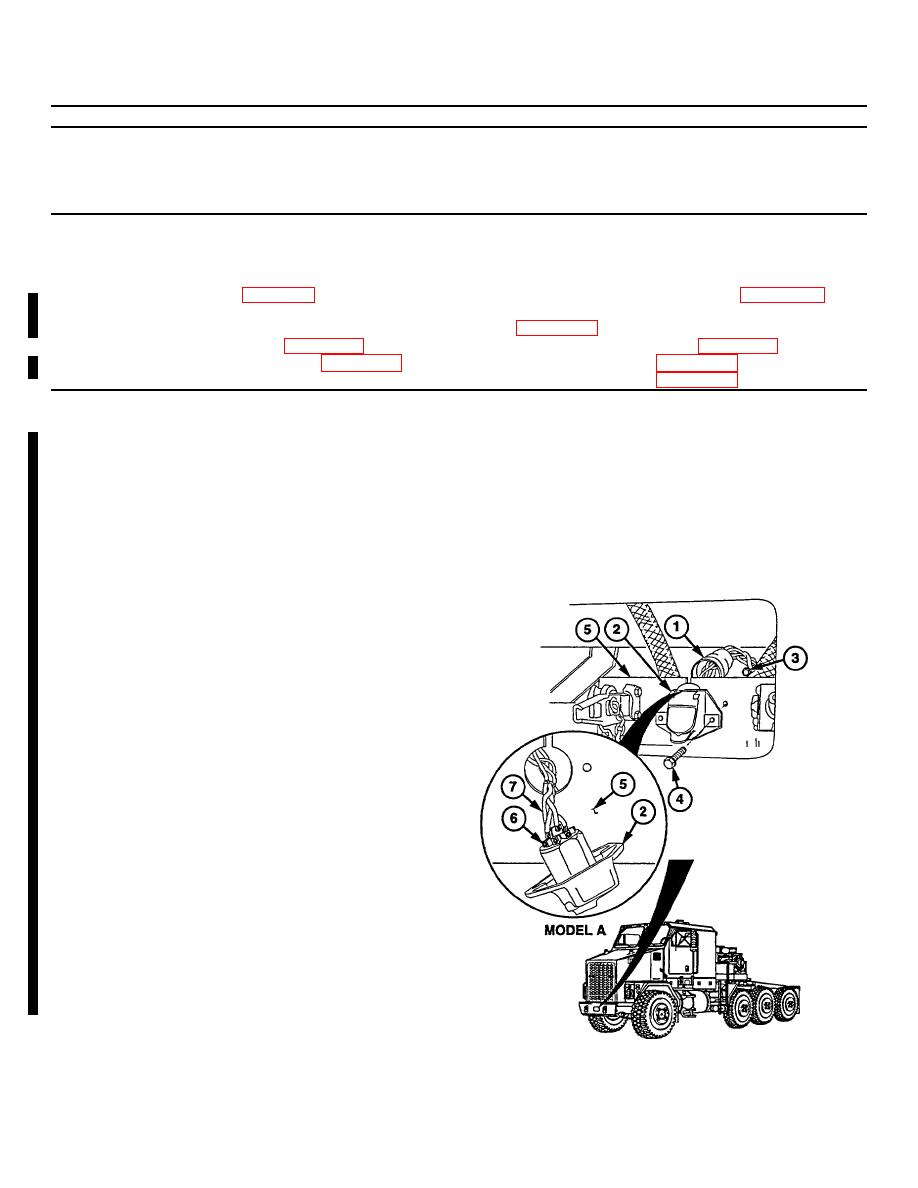
The HET Tractor has three 7-pin electrical connectors. One is located at front,
one at fifth wheel work platform, and one at rear of HET Tractor. All three
electrical connectors are replaced the same way. Front connector is shown.
Front connector has four wires.
Fifth wheel and rear connectors have six
wires.
There are two types of 7-pin connectors. Model B replaced Model A.
Model A has a rubber boot covering the back.
Model B uses rubber push on connectors on the back.
Do steps (1) thru (4) for model A connector.
Do steps (5) and (6) for model B connector.
a. Removal
(1) Separate rubber collar (1) from electrical
connector (2).
NOTE
Tag and
mark all wires
before
removal.
(2) Remove two locknuts (3) and screws (4)
from electrical connector (2).
Discard
locknuts.
(3) Separate electrical connector (2) from
mounting bracket (5).
(4) Loosen screws (6) and remove wires (7)
from electrical connector (2).
7-180 Change 2
|
|
Privacy Statement - Press Release - Copyright Information. - Contact Us |