 |
|||
|
|
|||
|
|
|||
| ||||||||||
|
|
 TM 9-2320-285-24-2
3-28.
STEERING SYSTEM MAINTENANCE (CONT)
d. Power Steering Gear (cont).
STEP
LOCATION
ITEM
ACTION
REMARKS
REASSEMBLY (cont)
13
f
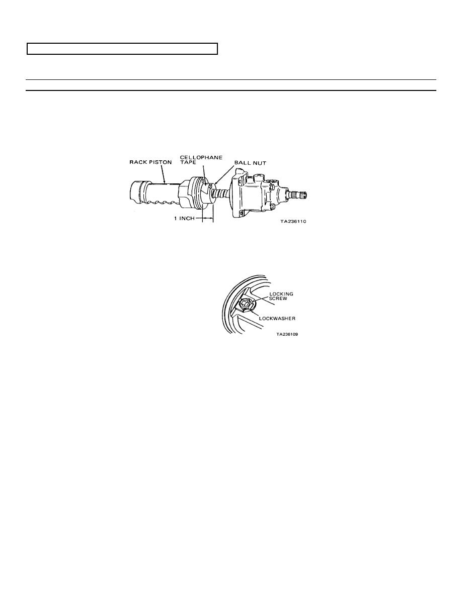
Rack piston
Install
Carefully slide large end of
(cont)
(12)
rack piston over worm shaft
of top cover assembly (1).
Align conical hole in ball
nut (38) with locking screw
bore in rack piston, and
slide ball nut into rack
piston until 1 inch of ball
nut is exposed. Remove
cellophane tape from ball
nut, and slide ball nut
into rack piston. Be sure
conical hole in ball nut is
aligned with corresponding
bore in rack piston
g
Locking screw
Install,
Lightly coat threads of lock-
(36) and lock
tighten,
ing screw (36) with hydrau-
washer (35)
and secure
lic sealant. Immediately
install locking screw (36)
with lock washer (35) and
tighten to 30-35 pounds
foot. Bend tab of lock
washer against face of
locking screw as shown
14
Side cover
a
Vent plug (21)
Install
Press in until flush
(4)
b
Bearing (22)
Install, if
Position side cover (4) on
removed
wooden block. Press bearing
(22) into bore of side
cover fully
c
Back-up washer
Install
(20)
d
Washer (19)
Install
e
Seal ring (18)
Assemble and
Position so OIL SIDE stamping
and seal (17)
install
is visible after installa-
tion
f
Retaining ring
Install
Use retaining ring pliers
(16)
3-270
|
|
Privacy Statement - Press Release - Copyright Information. - Contact Us |