 |
|||
|
|
|||
|
Page Title:
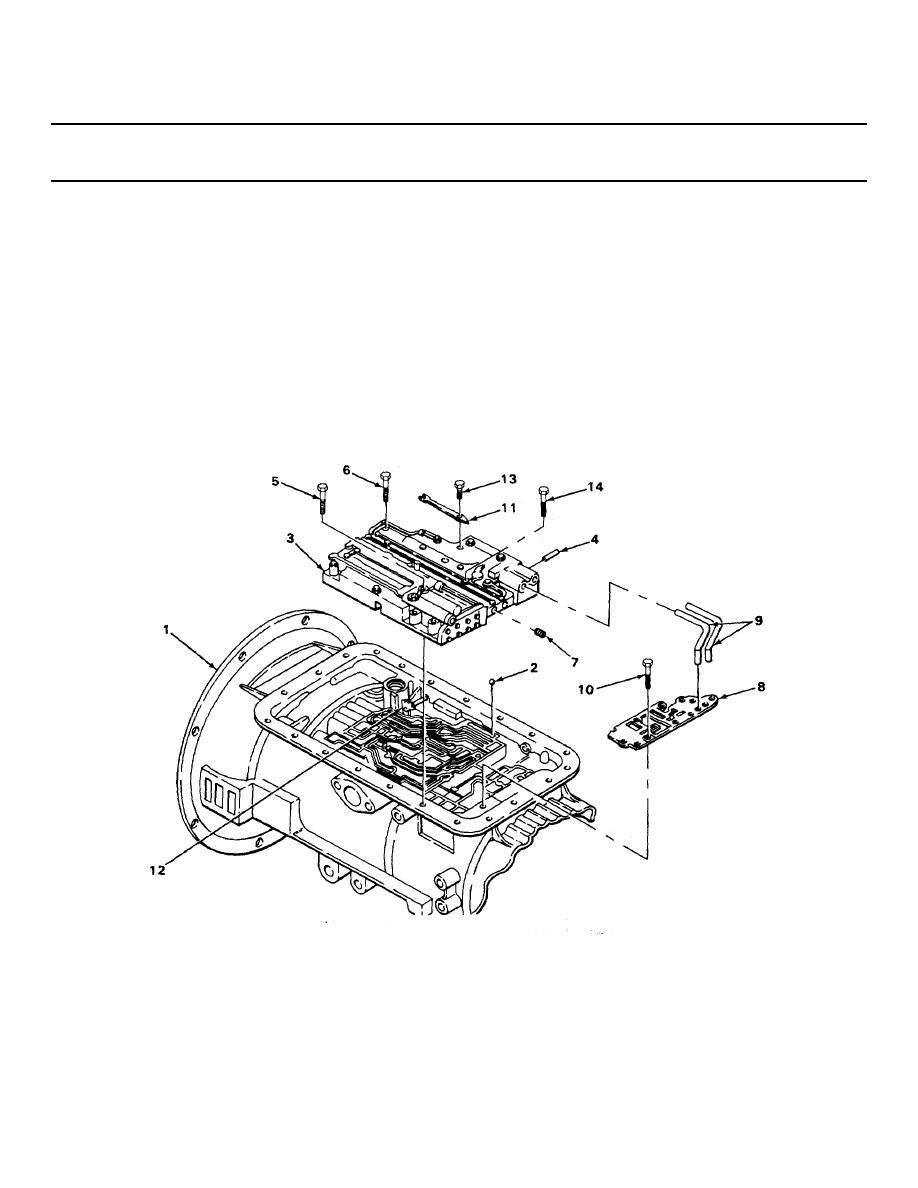
CONTROL VALVE ASSEMBLY INSTALLATION - CONTINUED |
|
||
| ||||||||||
|
|
 TM 9-2320-269-34-1
TRANSMISSION SUBASSEMBLIES - CONTINUED
ACTION
LOCATION
ITEM
REMARKS
CONTROL VALVE ASSEMBLY INSTALLATION - CONTINUED
127.
Detent spring and
Screw (13)
a. Place into position.
roller assembly (11)
b. Using 7/16-inch socket and ratchet
handle with 112-inch drive, screw in
until snug.
c. Using 7/16-inch s ocket and torque han-
dle with 1/2-inch drive, tighten to
8 - 12 ft-lb (10.8 - 16.3 N m) of
torque.
128.
Control valve
18 screws (14)
Starting from the center and working out-
assembly (3)
ward, using 7/16-inch socket and torque
wrench with 1/2-inch drive, tighten to
8 - 12 ft-lb (10.8 - 16.3 N m) of torque.
TA238421
2-687
|
|
Privacy Statement - Press Release - Copyright Information. - Contact Us |
