 |
|||
|
|
|||
|
Page Title:
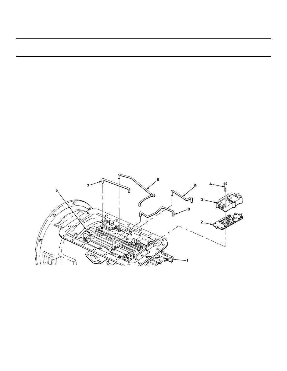
LOW SHIFT VALVE ASSEMBLY INSTALLATION |
|
||
| ||||||||||
|
|
 TM 9-2320-269-34-1
TRANSMISSION SUBASSEMBLIES - CONTINUED
ACTION
LOCATION
ITEM
REMARKS
LOW SHIFT VALVE ASSEMBLY INSTALLATION
129.
Oil transfer
Separator plate (2)
Place into position.
plate (1)
and low shift valve
assembly (3)
130.
Low shift valve
Seven screws (4)
a. Place into position.
assembly (3)
b. Screw in until snug, using 7/16-inch
socket and ratchet handle with 1/2-
inch drive.
c. Using 7/16-inch socket and torque
wrench with 1/2-inch drive, tighten
to 9 -11 ft-lb (12.2 - 14.9 N m) of
OIL TUBES INSTALLATION
131.
Control valve
Drive tube (6), main
a. Put in position in order shown.
assembly (5) and
knockdown tube (7),
b. Using plastic-face hammer, tap in
low shift valve
trimmer tube (8),
until seated.
assembly (3)
and low clutch
If tubes are not fully seated, they
feed tube (9)
will be in way of oil filter.
TA238422
2-688
|
|
Privacy Statement - Press Release - Copyright Information. - Contact Us |
