 |
|||
|
|
|||
|
Page Title:
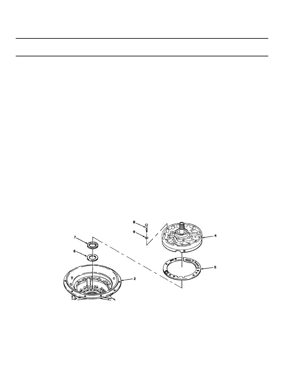
OIL PUMP AND FRONT SUPPORT INSTALLATION - CONTINUED |
|
||
| ||||||||||
|
|
 TM 9-2320-269-34-1
TRANSMISSION SUBASSEMBLIES - CONTINUED
ACTION
LOCATION
ITEM
REMARKS
OIL PUMP AND FRONT SUPPORT INSTALLATION - CONTINUED
116.
Transmission
Oil pump and front
a. Screw in two 3/8-16 x 6-inch guide
housing (2)
support assembly (4)
screws into opposite sides of trans-
mission housing.
b. Attach front support lifter to front
support assembly ground sleeve.
c. Attach portable floor crane to front
support lifter.
d. Aline holes with guide studs and holes
in gasket and transmission housing.
e. Using hoist, lower into place.
f. Remove lifting equipment.
117.
Oil pump and front
12 screws (8) and
a. Screw in.
support assembly (4)
new washers (9)
b. Screw in, until snug using 9/16-inch
socket, 6-inch extension, and ratchet
handle with 1/2-inch drive.
c. Replace two guide studs with screws and
washers, and screw in until snug.
d. Using 9/16-inch socket, 6-inch exten-
sion, and torque wrench with 1/2-inch
drive, tighten two screws 180 degrees
apart to 15 ft-lb (20.3 N m) of torque.
e. Repeat with two screws 90 degrees a-
round circle.
f. Tighten remaining screws in pairs 180
degrees apart.
g. Repeat entire operation and torque
all screws to 24 - 32 ft-lb (32.5 -
43.4 N m).
TA238420
2-685
|
|
Privacy Statement - Press Release - Copyright Information. - Contact Us |
