 |
|||
|
|
|||
|
Page Title:
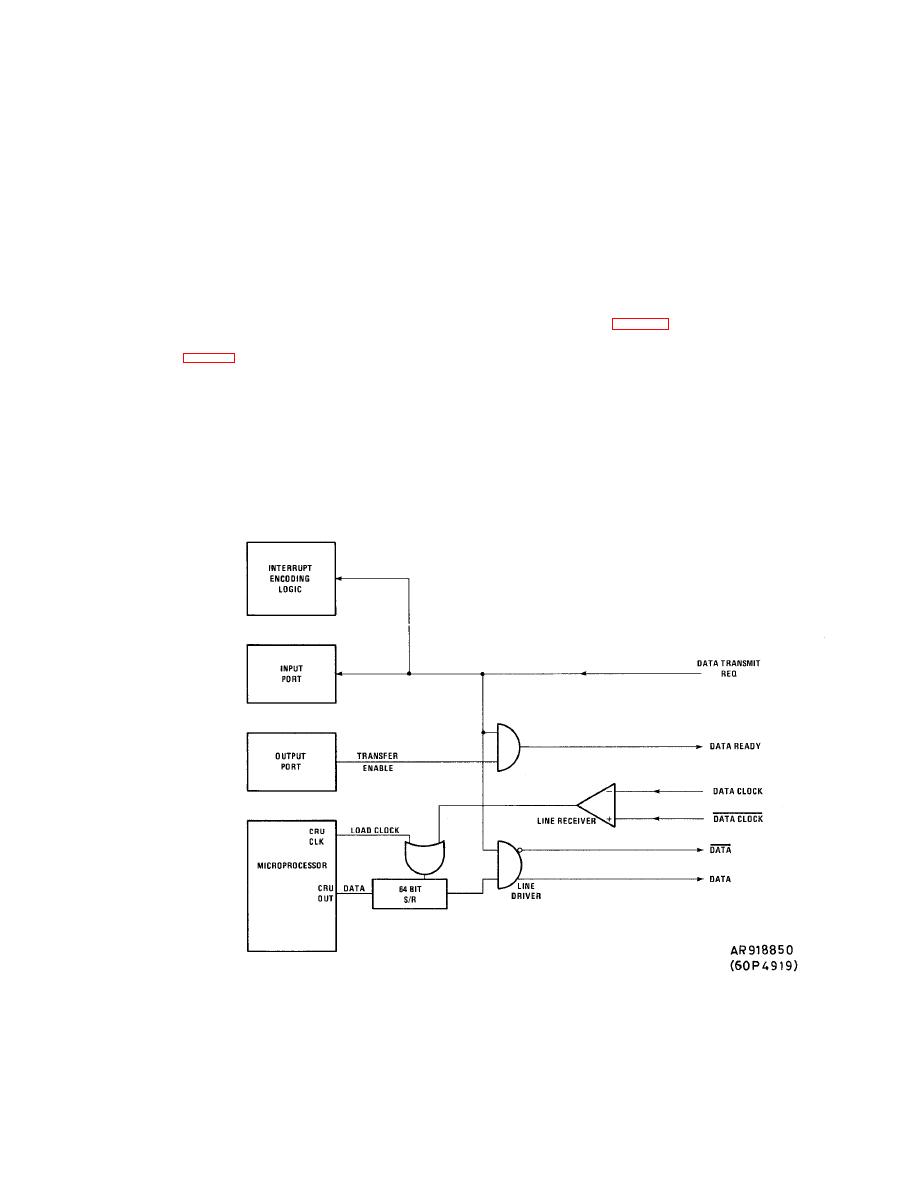
Figure 1-21. ADS to FCC Interface Block Diagram. |
|
||
| ||||||||||
|
|
 TM 9-1270-219-13&P
(a) A further 15 bits comprising two 7-bit
(a) The 64-bit shift register is updated from the
serial
output
of
the
clocked
by
a
status words and a total parity bit are accessible at AVIM
dedicated signal from the processor.
level test. Each bit of these words is the result of a BIT
r o u t i n e . The ADS buffer store is a 64 bit shift register
w h i c h is updated after termination of data transmission to
(4) P r o c e s s o r I n t e r r u p t s . Normal operation of the
the FCC.
A D S requires an interrupt to initiate loading of the output
buffer store after a data transmission to the FCC has been
(6) A n a l o g
O u t p u t s . A 12-bit binary value held in
terminated. The EPU Self Test switches also use interrupts
a portion of the Output Ports is converted to an analog
to instruct the processor to enter the self test routines.
value
through
the
Digital
to
Analog
Converter
and
p r e s e n t e d to all five of the output sample and holds on
(5) S e r i a l D a t a T r a n s m i s s i o n . Data is transmitted
the AIU card (fig. 1-24). Four more bits in the Output
to the FCC along a single dedicated serial line under FCC
Port are set with a code corresponding to one of the five
output
sample-and-holds
(Analog
Channel
Select).
By
control (fig. 1-21, 1-22 and 1-23). When the FCC requests
data, the Data Transmit Request discrete is enabled, and,
setting, and then resetting, the Analog Output Strobe
provided that the ADS shows a Data Ready discrete, the
momentarily
decoder
is
Bit,
the
One-of-Eight
FCC sends a clock signal. The ADS then responds by
enabled
and
one
only
of
its
output
lines
is
also
outputting
the
requested
data
in
the
form
of
six
momentarily
low,
the
enabled
enabling
consecutive 8-bit words, followed by a single parity bit
corresponding
sample
and
hold
to
latch
the
analog
making a total of 49 bits.
value.
|
|
Privacy Statement - Press Release - Copyright Information. - Contact Us |
